I have a way for first (shutting Iq of drivers and pucks) while I'm lazy to even think of mains killing
though , Papa naturally is obliged to make it foolproof , while I can't** make it (my own) proof of this fool
**(and doesn't need)
though , Papa naturally is obliged to make it foolproof , while I can't** make it (my own) proof of this fool
**(and doesn't need)
Last edited:
Conceptual Schematics XXII
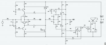
Well, I put together the conceptual FE and BE of the previous posts - to produce a possible iteration of the whole circuit.
I have simulated the whole circuit. Although I have not had the time to search
for the correct pspice-models of the semiconductors, it measures very well indeed with the IRFP240/9240 and the dubious models of the rest of the semiconductors.
Please take a look.
Attachments
Comments
R30, C4, C5 are not a necessity, they bootstrap the power-feed resistors
for a slightly better PSSR and a litter higher Open-Loop Gain. They may be left out.
The circuit features very low distortion. The Square-Law characteristics of each half of the circuit
produces lower order harmonics that readily cancels out in the complementary arrangement.
The bias regulator-circuit keeps the Idc VERY stable regardless of temperature variations.
It is possible to just use a silicon-diode and a voltage divider to create the required
reference voltage.
It is not necessary to use the temp-compensated voltage reference as shown.
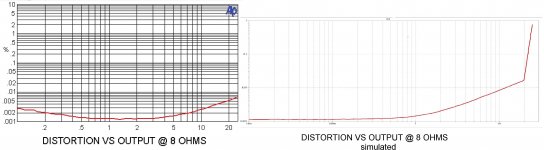
fft of output 20W in 8 ohms.
Bias is = 2.5 Adc
Voffset out = 1.5 mVdc


R30, C4, C5 are not a necessity, they bootstrap the power-feed resistors
for a slightly better PSSR and a litter higher Open-Loop Gain. They may be left out.
The circuit features very low distortion. The Square-Law characteristics of each half of the circuit
produces lower order harmonics that readily cancels out in the complementary arrangement.
The bias regulator-circuit keeps the Idc VERY stable regardless of temperature variations.
It is possible to just use a silicon-diode and a voltage divider to create the required
reference voltage.
It is not necessary to use the temp-compensated voltage reference as shown.
fft of output 20W in 8 ohms.
Bias is = 2.5 Adc
Voffset out = 1.5 mVdc
Last edited:
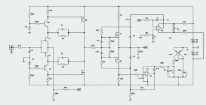
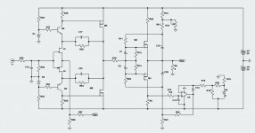
Conceptual Schematics XXIII - simplified
A few fellow diy:ers have expressed concerns about the complexity of the conceptual schematics and the number of OP amps and servos used.
Remember that this is not the original XA25 circuit, it is only a possible solution.
I am sure Pass Labs has a much better and more optimized circuit.
It is possible to slightly simplify the circuit though.
That would be to remove the DC offset servo and replace the reference voltage source with a simpler one.
But remember that it will exhibit thermal drift in "simple" simulations, but in real life it will work very nicely indeed (as long as the diode and the heatsinks
are not thermally coupled).
Please have a look:
Attachments
About 2 milliseconds, and then shutdown, regardless off how many
amps above 10A.
Is that over current protection necessary because there are no degeneration resistors that would otherwise limit the current? Is it recommended for safety reasons to implement that kind of over current protection also in our home brewed amps? Or does it just help to reduce the amount of amps that are returned to be repaired?
Mostly done for safety compliance. They think up all kinds of strange tests to do on our amplifiers some of them don't make much sense to me. We very seldom see an output stage failure.
Wayne: Because of DC coupling, what happens when a speaker is connected to the XA25 and the input source has an abnormally high DC offset, perhaps due to a bad capacitor in the output circuit? This could lead to a high over-current and damage the speaker.
The aforementioned safety standards also cover large DC offset.
We have a shut down circuit for various conditions, including high temperature,
over current, and DC offset.
We have a shut down circuit for various conditions, including high temperature,
over current, and DC offset.
uPC1237 fits the bill
at least that's what's written on pcb (certainly prototype , so not populated few parts) , on few XA25 , I have here in OPLDF
at least that's what's written on pcb (certainly prototype , so not populated few parts) , on few XA25 , I have here in OPLDF

Hi,
A quick question for you guys. How comparable is the XA25 to a F5T v2 in terms of driving low impedance loads? I've been thinking of picking up a pair of Magnepan .6 or maybe a model up. The .6 are 4 ohm across the frequency span, but somehow Magnepan speakers have been reported to be difficult to drive.
I have a F5T v2, it's a dual mono to the power cord, single chassis with a tons of capacitance.
The drive capability of the XA25 is just killer. I could save myself $4k, if the F5T v2 will do the job. When I reading the F5T article, I get a little confused regarding the load drive capability between the F5T v2 and v3 versions.
I know. Just try the Magnepans with the F5T, but there's the whole buying and shipping aspect. Perhaps I'm just trying to get as much info before dropping any $$.
Thanks,
Vince
- Home
- Amplifiers
- Pass Labs
- Pass XA25?