...I don't particularly feel good about posting circuits that attempt to copy a circuit in a thread labelled as such...
Thank you picoDumb for the reminder. Point taken...
There is no ban against "conceptually" discussing a circuit on
diyaudio, as there is nothing unique to the circuits we are discussing, and we are not disclosing exact
schematics with component values.
We are merely discussing "possible" solutions to the problems.
Remember, this is DIY-AUDIO. Anything may be discussed here, even commercial offerings.
IC manufacturers often disclose "conceptual" designs of their products (AD797).
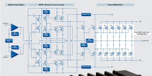
That is the case even in audio. For example, Accuphase always discloses their conceptual
design schematics of their products (see attached pic below)
Any unique design, may be protected through international patents (super-symmetry, aleph and so on).
Even then it may be openly discussed since it is public knowledge.
Pass labs products reflect Mr Pass' vision.
I believe it would not possible to create a replica "clone" or an identical "copy" of the circuit
from the conceptual schematics presented here.
The conceptual schematics here are almost exact copies of what Mr. Pass has kindly shared
earlier (Sony VFet-fe and so on).
Mr Pass' designs are intriguing, since he started in the 70's with:
- fairly complex SE-FE/PP-BE.
- then to EXTREMELY simple SE,
- then more complex fully PP-FE/PP-BE.
It is interesting to understand why he did abandon the very simple SE designs in his commercial offerings.
That really goes against everything Pass Labs stands for (the most simplistic circuit realization).
There are extremely few reviews on the XA-25, so we really do not know much about it, and those few available reviews are mixed.
A couple of audiophiles (in another forum) who also own other XA products informed me that XA25 -
although VERY GOOD - does not quite match the level of "elegance" and "grace" on complex music presented by its bigger siblings.
And this is perfectly fine, since XA-25 is a scaled-down version of its bigger brothers.
It would be impossible to put people in jail for discussing or disclosing conceptual designs, unless they are protected by international patents.
Even then, it is only possible to prevent commercial production of designs that can be traced back to the patent description.
As I mentioned earlier, if our dear Mr Pass, or any other employees of Pass Labs, or moderators find any part of
our discussions inappropriate, please contact us.
With that being said, there is really not much more to discuss about XA-25 conceptual design, so we can basically stop right here...
Attachments
Last edited:
...........
It is interesting to understand why he did abandon the very simple SE designs in his commercial offerings.
That really goes against everything Pass Labs stands for (the most simplistic circuit realization).
.......
you got that wrong
...........
.........
With that being said, there is really not much more to discuss about XA-25 conceptual design, so we can basically stop right here...
that too
it's already written several times, as direct reply to you , what are most interesting details of XA25
besides that , everything else is pretty easy deduction task for regular Papaland residents
besides that , everything else is pretty easy deduction task for regular Papaland residents
Yep. I feel like many of us have had fairly close (maybe even very close) conceptual schematics since maybe a week after the XA25 announcement. But, the real trick is biasing the hockey pucks and preventing thermal runaway. Being a non EE, I solved the problem in my first version of a similar amp in a terribly naive way. It works and sounds great, but is definitely not the most elegant solution and will likely not allow for class AB operation without thermal drift.
Last edited:
Back End - Possible Solutions
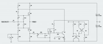
There is a lot of discussion about the possibility of regulating the bias current through the back end of the amplifier.
I have seen some really nice solutions in some of the threads here, and the biggest problem seem to be the temp drift.
The attached solution might work fairly well, as the reference is temp compensated, and the Offset voltage is hence regulated, since it is a function of the bias current.
It is my solution and a very simple one, and I would like to share it with the rest of you.
Attachments
Greetings Mr Colburn.
Thank u for the vote of confidence.
Well, you are one of those selected few able to make that comparison.
I will try to simulate the circuit once I get my ltSpice running. (I installed
the newest version and it crashed).
Nothing exciting... possibly the temp-compensated reference (although not tested yet).
The remaining circuit is an appropriately slow comparator, with low
offset error, to track any low-f, Id-change due to drift.
The comparator might be incorporated into the amp....I'll have to take
a closer look.
Another interesting side-effect of the double mirrored reference is that the sense resistor may be kept
low, < 0.1, and unipolar, to avoid any subsequent headroom loss.
As mentioned, I could not test it yet, I'll get back to you once I get the SW running on my PC.
Last edited:
Back End - Possible Solutions - Simulations
Well....I have run some simulations on it and the presented circuit above works as advertised.
Very nicely regulating the bias current of the output Follower Stage.
I am having some major problems with the ltspice...I think it might be my PC and not
the SW itself.
I ran two simple simulations: one at 20 deg, and one at 80 degrees.
The current changed from 1.502 A till 1.508 A.
I would call this a VERY tight regulation of operating current.
Last edited:
Back End - Possible Solutions III
As mentioned yesterday, it would be possible to simplify the circuit a little.
So here it goes.
Once again:
These are my own solutions mine.
These are not copies or clones of anything or anyone elses design.
In the spirit of sharing, I would like to share these solutions with the rest of you.
As mentioned yesterday, it would be possible to simplify the circuit a little.
So here it goes.
Once again:
These are my own solutions mine.
These are not copies or clones of anything or anyone elses design.
In the spirit of sharing, I would like to share these solutions with the rest of you.
Attachments
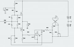
Back End - Possible Solutions III - Simulations
The simulation results are equal to the first circuit - as they should be.
Two simple simulations were performed:
at 20 deg: Idq = 1.501 Adc, Vdc_out = +6.43 mVdc
at 80 deg: Idq = 1.508 Adc, Vdc_out = -20.1 mVdc
I am not 100% certain about the simulation results, as I am having major issues with ltSpice.
But these are very simple circuits and the simulated results are fairly indicative of what to expect in implemented circuits.
Surprisingly quite a few people have emailed me, stating that they are really worried about the use of OP in the circuit.
Does it affect the sound quality? It might, as any parallel-servo circuit may.
Before I get more mails:
Yes, it would be possible to use transistors instead of the OP. Maybe it would be preferred.
No, I do not know how to further simplify the circuit without sacrificing performance.
Cheers
Last edited:
Does anyone have an idea about the actual meaning of the following specification from the XA25 User Manual? https://passlabs.com/amplifier/xa25
"Peak Current: 10 Amp output (200 Watt peak into 2 ohms)"
My question is whether the protection circuit shuts the channel down if at any instant the current thru an output FET exceeds 10A, or does it require the averaged current thru a FET over some time interval (like a few milliseconds) to exceed 10A?
it can't be instantaneous , it requires some time for integration (right term ?) ..... also preventing reaction just from sparrow's fart
🙂
🙂
How much integration time? If it is 10ms, then a 1ms 90A pulse will pass through without triggering shutdown. Maybe that is OK since the amp-seconds and watt-seconds (Joules) figures are not excessive.

Thanks. That is about what my simulations can obtain.About 2 milliseconds, and then shutdown, regardless off how many
amps above 10A.
Not exactly when the pulse amplitude is on the order of 1KW or more.perhaps a hummingbird fart
I'm still ambivalent about that ....... how to solve it ....... killing output gates is enough ...... or with thyristor at mains side
There is an easier way that shuts down the bias currents of all stages without shutting off the transformer. Keep searching and you will be rewarded.I'm still ambivalent about that ....... how to solve it ....... killing output gates is enough ...... or with thyristor at mains side
- Home
- Amplifiers
- Pass Labs
- Pass XA25?