Simulations II
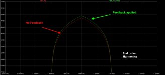
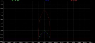
As can be seen on the zoomed-in graphs, the amplitude of the
overtones are all higher!
As we go towards the higher numbered harmonics, the more profound the difference
between the No-Feedback and fedback-Amplifier becomes.
The amplifier that features 15 dB of feedback now show clear signs of much higher
amplitudes on higher order harmonics!
2nd, 3rd, 4th, 6th, 8th, and so on:
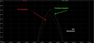
Attachments
Simulations III
What is wrong with this picture?
Feedback is a SUBTRACTIVE process, in particular when applied to such low frequency
signals in such a simple and linear topology.
But we are getting additive behavior, that is mathematically not possible.
So what is the problem???
What is wrong with this picture?
Feedback is a SUBTRACTIVE process, in particular when applied to such low frequency
signals in such a simple and linear topology.
But we are getting additive behavior, that is mathematically not possible.
So what is the problem???
Simulations IV
Since higher ordered harmonics are being created, it is highly unlikely that it is
due to application of feedback, specially degenerative feedback.
These higher ordered harmonics are possibly due to a slight signal compression somewhere in the output circuit loop.
A decrease on the Vds headroom might cause this type of behavior.
But how can this be verified?
Feedback, specially as done with a resistive
degeneration, into a resistive load, in such a simple circuit, should not give
rise to higher amplitude of higher order harmonics...
It changes the spectral content. For a given distortion figure, the ratio of
higher / lower order harmonic increases.
This is well established mathematically and in experiment.
At the same time, you don't necessarily want to get all that excited about it,
as the effect diminishes dramatically with overall distortion levels. That is
why you see the examples having 10% 2nd harmonic. If they were .01%,
then it becomes negligible IMHO. A good reason to design intrinsically
linear circuits in the first place.
Simulations V
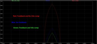
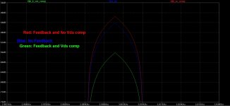
Let's create another version of the test signal, where the loss of headroom due to
the degenerative feedback element has been compensated for.
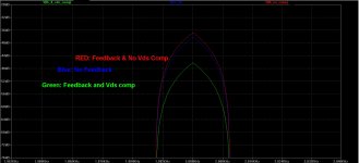
And lets put all these graphs together and compare:
Blue = No Degenerative Feedback
Red = Degenerative Feedback applied
Green = Degenerative FB and Vds compensation applied
Lets see:
2nd, 3rd, 6th, 8th and so on...
Let's create another version of the test signal, where the loss of headroom due to
the degenerative feedback element has been compensated for.
And lets put all these graphs together and compare:
Blue = No Degenerative Feedback
Red = Degenerative Feedback applied
Green = Degenerative FB and Vds compensation applied
Lets see:
2nd, 3rd, 6th, 8th and so on...
Attachments
hot-rod them and bridge them
no need for multiples
if you need even higher power figures , either start/continue work in PA , or buy better speakers , more suited for Home Shrine
no need for multiples
if you need even higher power figures , either start/continue work in PA , or buy better speakers , more suited for Home Shrine
Simulations V
Let's create another version of the test signal, where the loss of headroom due to
the degenerative feedback element has been compensated for.
...
Interesting... how is this Vds compensation done? Do show your Sim so that we can understand 😉
Relevant old thread revival
http://www.diyaudio.com/forums/solid-state/120673-gr-25-a.html seems particularly relevant here...
http://www.diyaudio.com/forums/solid-state/120673-gr-25-a.html seems particularly relevant here...
Archived DIY Audio Kits Reviews, Projects And Articles On Enjoy the Music.com is there last place I saw anything by Grey. There some good articles in that archive 🙂
Interesting... how is this Vds compensation done? Do show your Sim so that we can understand 😉
---------------------------------------------
It is exactly according to the circuit description in the Pass Labs documentation "Distortion & Feedback".
That is:
- Single SE MosFet stage
- Biased at 2 A.
- 8 ohm resistive load.
- 11 V across the Q.
- one circuit (cir. 1) with no degenerative feedback
- the other one (cir. 2) with 15 dB degenerative feedback applied.
As described in the Pass Labs paper, the circuit with 15 dB feedback clearly showed significantly higher amplitude on higher order harmonics.
This was verified to be correct by performing Transient Analysis simulations.
In order to examine why this was the case, an additional circuit (cir. 3) was created in which appr 3V of voltage loss
due to 15dB degenerative feedback has been compensated for - simply by increasing the Vds by an equal amount.
As depicted in the SIMPLE simulation results, this circuit does not suffer from the higher order harmonics as the test circuit proposed by Mr. Pass.
In actuality, cir. 3 has LESS distortion than the No Feedback circuit.
This result contradicts the claims in the Pass Labs document.
This led me to suspect that the higher-ordered harmonics created in cir. 2 might be due to some other mechanism than feedback alone.
Feedback in such linear, LOW FREQUENCY circuits will not create higher ordered spuriae.
PLEASE NOTE:
------------------------------------------------------------------------------
No body is claiming right or wrong, and no body is trying to insult anyone.
We are merely examining the presented data a little more carefully. That's all.
That is what engineers do, it is not an insult or disrespect towards anyone.
Sugar-coating or serving everything with cream and honey is not part of the engineering doctrine.
If this stuff bothers you, go read something else for a while and then come back.
cheers
Last edited:
Listening Tests
Listening tests were performed the whole day yesterday, on a complementary JFET/MosFet Front End, with degenerative feedback
applied (originally) on both stages.
The amplifier Back End is similar to that of BA amplifiers, with a bank of 3 pairs of complementary MosFet followers biased at 3 amps
per channel at 32 Vdc PSU and matched and adjusted for lowest THD.
The Front End features the same JFET pair as Pass, coupled to two old Harris devices: 520 and 9520.
These are verticals with HUGE Gm figures.
For that reason removing the degeneration proved to be a frustrating exercise, as no amount of heat sinking cured their tendency to run-away.
The no-degeneration problem was solved a little differently (CPU copper heat-sinking) and listening tests (with the FE with no degeneration) was performed.
Here's what we noticed:
--------------------------------------------------------
The sound got "rounder" and slightly "deepened".
The previously "sharp" and tight focus that helped create air around the instruments, and a wealth of details was now much reduced.
The sound acquired a pronounced level of "warmth" that almost felt a little too exaggerated at first.
Like increasing the RED component on the older color TVs.
The sound-stage felt a little expanded.
The lower octaves exhibited the same "roundness" and richer texture, with some loss in the apparent "slam".
The differences in the mid octaves were much less pronounced - maybe a little bit - in favor of the
No-Degenerative version.
Looking at my notes, I see the word "MELLOW" written several times.
Bandwidth measurements were identical on both versions, so was the THD figures....The sound was NOT.
....very interesting results....
Last edited:
In actuality, cir. 3 has LESS distortion than the No Feedback circuit.
This result contradicts the claims in the Pass Labs document.
There is no claim that it has more distortion. The claim is that the
spectral content has become more complex, with a greater relative
percentage of higher order harmonics.
Last edited:
There is no claim that it has more distortion. The claim is that the
spectral content has become more complex, with a greater relative
percentage of higher order harmonics.
This is true and very easy to observe if you have a distortion analyzer.
veering wayyy ot but fwiw....sounds like you need to do a bit more homework ...
...sounds like you need to take a closer look at the graphs...
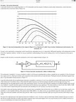
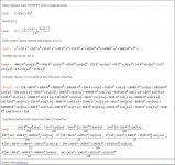
Here is the mathematical analysis of the Ideal Square Law MOSFET with Degeneration.
---------------------------------------------
Thank you Ihquam for the info.
I'll take a closer look and try to understand it ;-)
-------------------------------------------------------There is no claim that it has more distortion. The claim is that the
spectral content has become more complex, with a greater relative
percentage of higher order harmonics.
Thank you Mr Pass for your response.
By performing a very simple simulation, the effects you mentioned in the article are clearly visible, even in the simple simulation.
But as you know, degeneratvie feedback, specially in such a worst-case-scenario, where the impedance of the degenerative element is
almost 20% of the output impedance, will effect the output voltage conditions quite substantially.
Applying 15dB of degenerative feedback, specially when the Vds loss (statically, but ideally even dynamically) is compensated for
will not lead to distortion, it would be impossible.
Thank you again for taking the time to reply.
Last edited:
Simulations VI
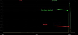
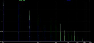
Please take a look at the picture below:
Blue graph is the output signal at 1W into an 8 ohms load,
exactly according to the circuit example in the Pass Labs document.
Green is the output signal of the amplifier with 15 dB degenerative feedback.
As can clearly be seen, there is substantial amount of higher order harmonics being created in the 2nd amplifier that features 15 dB of degenerative feedback.
Attachments
- Home
- Amplifiers
- Pass Labs
- Pass XA25?