and , yeah, it's a Berserker
Full Body Latte with extra Foam ?
(© idiocracy)
No. The open loop gain is lower than the sims suggest because they
don't represent the details of the actual circuit. In the XA25 I can set the
open loop figure easily and arbitrarily.
I haven't used frequency compensation (or output zobels) in PL or FW
product for many years. But the XA25 is new, and being a belt and
suspenders kind of guy, I put the output zobel on the XA25 just as
cheap insurance.

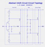
This is probably a better representation of the essential elements of the actual circuit. I believe that it addresses the elements that define the open-loop gain.
Attachments
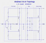
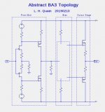
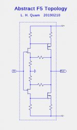
While I am at it, here are abstract topologies for the XA.8, BA3, and F5:
Attachments
Last edited:
Thank you so much for providing these abstract topologies. They make it easy to spot things not easily understood; at least by me. For example, I am making it my business to figure out why the bias resisters connect to the for XA connect to the VAS out rather than to ground. I suspect the reason is fundamental. Back to the project descriptions. Better to figure it out now than to burn the house down.
For the XA25 typology, the VAS load was removed as were the gate resistors compared to your 20190114 account. I don't understand how this "addresses the elements that define the open-loop gain." I will get there.
For the XA25 typology, the VAS load was removed as were the gate resistors compared to your 20190114 account. I don't understand how this "addresses the elements that define the open-loop gain." I will get there.
The F5 is common source with voltage and current gain; no? The XA OS is voltage follower with current gain only; no? Why is "everything F5?"in short , everything is F5

in short , everything is F5
You know the difference between source and drain follower?
😀😀😀😀
Thank you so much for providing these abstract topologies. They make it easy to spot things not easily understood; at least by me. For example, I am making it my business to figure out why the bias resisters connect to the for XA connect to the VAS out rather than to ground. I suspect the reason is fundamental. Back to the project descriptions. Better to figure it out now than to burn the house down.
For the XA25 typology, the VAS load was removed as were the gate resistors compared to your 20190114 account. I don't understand how this "addresses the elements that define the open-loop gain." I will get there.
The gate stopper resistors were removes from the daigram since they are not essential in presenting the topology.
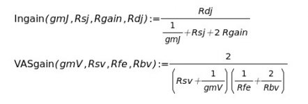
The open-loop gain depends on the FET transconductances and the resistors shown, except that the feedback resistor from Out is removed.
An additional drawing is in the works that explains this in more detail.
Here is a generic schematic for XA25, XA.8, ... front-end topology and the calculations for the voltage gains of the Input and VAS stages. This is simplified in that the FETs are assumed to be ideal complements, ie. have identical transconductances.
Attachments

"Remove Rfb for OLG calculation?" Remove Rfb and, thus, break connection? That is, remove negative feedback from the OS output? Hence, open the loop? Rfe (load) causes the "puppy" to be tired and, thus, "happy?" Wild guesses. Thanks so much for posting this information.
You know the difference between source and drain follower?
😀😀😀😀
follower...... what's that?

Here is a generic schematic for XA25, XA.8, ... front-end topology and the calculations for the voltage gains of the Input and VAS stages. This is simplified in that the FETs are assumed to be ideal complements, ie. have identical transconductances.
You are omitting that the XA.8 is a balanced circuit.
XA25 Break in Update
The BCD-3/HPA-1/XA25 components have reached 1500 hours of continuous operation. During this time I acquired a new rack. All components, except the XA25, are weighted and on points. The XA25 floor stand (nearly 100 lbs of Corian) is on points. I have been tweaking power and signal cables. Every week or so I listen to a few reference recordings.
This system just keeps getting better. I don't know which component is contributing to change at this late time. Perhaps me. The resonance of voices is still improving. I could diagnose a sinus infection. Blackness is still improving. The system was stunning out of the gate. More stunning after a month. And even more stunning after two months. Simply unbelievable.
Last edited:
You are omitting that the XA.8 is a balanced circuit.
Closed loop voltage gain of XA.8 was interesting.
Its not just resistor values involved.
- Home
- Amplifiers
- Pass Labs
- Pass XA25?