In either position of the bypass switch it's just buffering a buffer.
So what's the purpose of the buffer buffer?
I am too cheap to duplicate parts in real product.
Must have been feeling generous when drawing that schematic.
😛
Must have been feeling generous when drawing that schematic.
😛

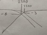
I guess the SK vs LK links work like this: In the LK (Linkwitz) position you cross at e.g. 2200 Hz and with both HP and LP 6 dB down. In the SK (Sallen-Key) position you keep the HP as is, while the LP is changed so it falls off at an increased frequency, namely such that it crosses the HP at 3200 Hz, where both HP and LP are 3 db down.
I tried a LTSpice simulation varying the resistors by the .step function, and got LP and HP curves all over my screen! I choose semi-arbitrary values for the resistors, starting at 2.34375k stepping with that number up to ~300k.
Very nice crossover, NP!
/RK
I tried a LTSpice simulation varying the resistors by the .step function, and got LP and HP curves all over my screen! I choose semi-arbitrary values for the resistors, starting at 2.34375k stepping with that number up to ~300k.
Very nice crossover, NP!
/RK
Thank you.
I put SK and LK on the board screening because they were the "obvious"
values that people want.
In point of fact they are rarely the optimal settings, as they don't account
for driver phase and amplitude response.
Siegfried historically dealt with this by creating additional eq and phase
correction for drivers so that they would work with the crossovers, a
case of deconstruction and synthesis.
The alternative I usually employ is to fool around with the pole values
of the filter until they give me what I want. Routinely this can achieve
a similar result, it's advantage being that the circuit is simpler.
Sorry for asking,
Do you think this will be available by the end of july? I have some projects to finish, one being an open baffle pure audio and other the diy vfet.
Thank you for all
Do you think this will be available by the end of july? I have some projects to finish, one being an open baffle pure audio and other the diy vfet.
Thank you for all
Thank you.
I put SK and LK on the board screening because they were the "obvious"
values that people want.
In point of fact they are rarely the optimal settings, as they don't account
for driver phase and amplitude response.
Siegfried historically dealt with this by creating additional eq and phase
correction for drivers so that they would work with the crossovers, a
case of deconstruction and synthesis.
The alternative I usually employ is to fool around with the pole values
of the filter until they give me what I want. Routinely this can achieve
a similar result, it's advantage being that the circuit is simpler.
You're welcome.
I imagined the concept as in the attached drawing.
Attachments
Do you think this will be available by the end of july? I have some projects to finish, one being an open baffle pure audio and other the diy vfet.
I am counting out and bagging parts for 100 base kits (pcb + fets) and 100
kits with all the resistors and capacitors.
I am counting out and bagging parts for 100 base kits (pcb + fets) and 100
kits with all the resistors and capacitors.
Wow. Sweet.
When should I start refreshing diyaudio store page?I am counting out and bagging parts for 100 base kits (pcb + fets) and 100
kits with all the resistors and capacitors.
I am counting out and bagging parts for 100 base kits (pcb + fets) and 100
kits with all the resistors and capacitors.
😱 i will not sleep until i can buy it. The open baffle and the monoblocks are waiting for more than a year!
Thank you for your work
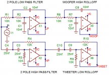
This is only the electric side of the crossover. In the real world, you need to use the acoustic respsonses of the drivers and adjust to suit.
will it be possible to get the pcb and the bom only ?.
Sure. BOM is free.
You can buy the base kit and throw away the Jfets and the resistors
that match to them.
BTW the board pinouts for the Jfets are DSG
If there was enough demand we could offer a pcb for the Toshiba or
Linea Systems parts.
- Home
- Amplifiers
- Pass Labs
- Pass Labs B4 crossover questions