Boy oh boy is it wrong to make the universal blanket assumption "it is ALWAYS difficult to drive both high impedance and low impedance headphone loads".
A simple and shockingly obvious counterexample proves this false.
Build an audio power amplifier, design it to drive 4 ohm loads. There are textbooks (Duncan, Self, Cordell) which tell you how to do this. Inside the chassis, connect an 8 ohm, 100 watt resistor between the amplifier output and ground. This costs about USD 15 per channel, less than a stereo pair of vacuum tubes. Less than a stereo pair of high end speaker binding post doublets (SPKR+ and SPKR-).
Voila, if you connect a high impedance load your amplifier sees 8 ohms at its output. If you connect a low impedance load (12R) your amplifier sees 4.8 ohms at its output. All comfortably within the design window and all easily dealt with.
Duh. Put an exclamation mark! if you wish
_
Terry,
Great it worked out and you like the sound.
If you would like to take it a step further you might want to build a version with a dual mono version or one with separate regulators for each channel. 😀
Jam
Great it worked out and you like the sound.
If you would like to take it a step further you might want to build a version with a dual mono version or one with separate regulators for each channel. 😀
Jam
Build an audio power amplifier, design it to drive 4 ohm loads. Inside the chassis, connect an 8 ohm, 100 watt resistor between the amplifier output and ground.
Like in the ACP+ :
"Of particular note, the gain circuit has been optimized around a 32 ohm load, and performs best at this impedance."
So design the HPA for 16R.
Have a rotary switch to switch a parallel resistor to the headphone :
33R for 32R phones
24R for 50R phones
22R for 65R phones
20R for 100R phones
2x 33R // for 300R & 600R phones
Could not resist, 😉
Patrick
Mark,
You sound like someone that like to comment but has little practical experience building working products and are limited to what you learned in school.
For one, the choice of voltage rails is important as are the choice of devices Their characteristics when working with different rail voltages changes and this is particularly important when working with mosfets.
Any audio engineer worth his salt knows that some times (for example) the best devices can not be used for high powered amplifiers. So you have to make a compromise when selecting devices. This is also compounded by the fact that when raising the rails the topology might have to change ie. use of cascodes etc which in turn can cause stability issues and compromise performance when you correct for it.
If you read the thread, I advised Jeff to change the topology of his amplifier for the above reasons. Ohm's Law is not going to help you here with your argument which is simplistic at best. Trying to bring Duncan, Cordel and Self into this is pointless in this instance.
I would suggest that you look at a wide range of headphones and understand their differences (which are huge) and their drive requirements and then consider your design (We are working with phones that vary as low as 12 ohms to as high as 700 ohms not to mention different efficiencies)......what power rails you need, what topology would you use, what compromises you have make with your choice of rails, devices and associated components? Not as simple as you think.
Regards,
Jam
Last edited:
Jam,
The idea of a parallel resistor was mentioned by Nelson in his ACP+ article.
https://www.firstwatt.com/pdf/art_acp.pdf
At the bottom of page 2.
Best regards,
Patrick
The idea of a parallel resistor was mentioned by Nelson in his ACP+ article.
https://www.firstwatt.com/pdf/art_acp.pdf
At the bottom of page 2.
Best regards,
Patrick

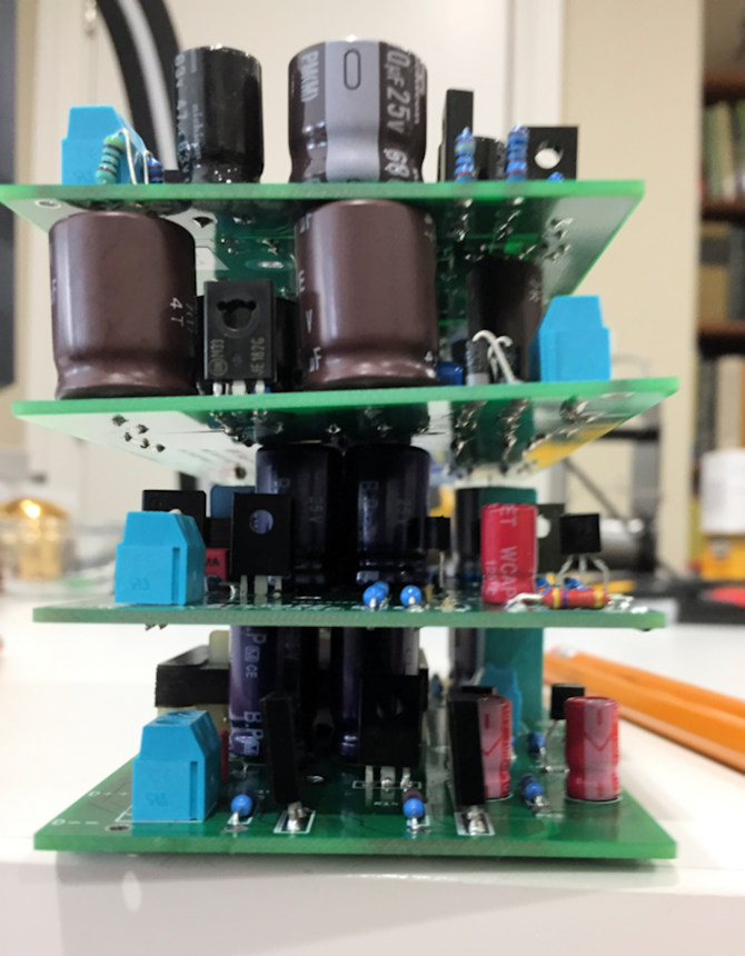
Thanks for your feedback, Jam. Here's a pre-release photo of the four "front end" cards I designed at Nelson Pass's request, which mate with his DIY Sony VFET amp. The amp is partitioned into two separate boards, encouraging DIYers to mix and match. The output power stage, using long out-of-production VFETs in TO-3 packages, bolts to the left 2/3rds of the heatsink, and one (your choice) of the "front end" card bolts to the right 1/3 of the heatsink. According to Nelson, these amps are going to be released by the diyAudio Store "real soon now" which I interpret to mean, before May 1st.
Since nothing is officially released yet, the photo is only a teaser, revealing precious little about the actual products. Full disclosure "real soon now".
Mix and match power amps seem to be increasingly popular with diyAudio members. Slicing off the "front end" of the First Watt M2 and putting it on a daughter card results in the "M2x" amp in the diyAudio Store. At least eleven different daughter cards have been released, that I'm aware of, and probably more that I don't know about. The most recent one from me uses the skittish thoroughbred "AD797", along with a few countermeasures to tame its propensity for oscillation.
Click on the image to see it full size and undistorted
_
Last edited:
...never say anything negative nor condescending.
...and vice versa. Mutual respect and long-running friendship can be more important than always agreeing on every little thing.
Mark,
I suspect that your work with the AD797 might center around pin 8 of the IC.? 😉
Well there is where I would look to solve stability problems.
Regards,
Jam
I suspect that your work with the AD797 might center around pin 8 of the IC.? 😉
Well there is where I would look to solve stability problems.
Regards,
Jam
Last edited:
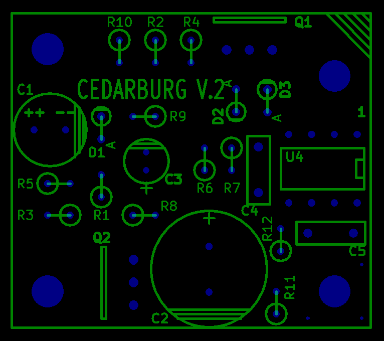
Schematics, photos, and design discussion are here on diyAudio. The daughter card name, is the best search term to use:
Cedarburg
which was suggested to me by Scott Wurcer. He was the circuit designer of the AD797. Cedarburg is a town in his boyhood state of Wisconsin.
_
Cedarburg
which was suggested to me by Scott Wurcer. He was the circuit designer of the AD797. Cedarburg is a town in his boyhood state of Wisconsin.
_
Can i used for the Ksa992, Ksc1845 the Ztx450,550 or the Original Mps8098 and Mps8598 from Motorola.
Thanks Michael.
Thanks Michael.
Last edited:
Thank you very much, I must find this transistors, in digikey and mouser they have in 48 weeks.
Regards. Michael.
Regards. Michael.
I'm a believer! At first I was sceptical. I read about it in many different posts. How would they even get the smoke in there? Then there it was. I plugged the amp in for the first time and saw the magic smoke!
Now I need a new capacitor (C60). Installed backwards. Ugh. I used the same circuit that Jeff posted. Post #191 has the pdf. Is there anything else I should be worried about, or just replace the cap and carry on?
Now I need a new capacitor (C60). Installed backwards. Ugh. I used the same circuit that Jeff posted. Post #191 has the pdf. Is there anything else I should be worried about, or just replace the cap and carry on?
- Home
- Amplifiers
- Pass Labs
- Pass HPA-1, what do we know?