It's got lots of mounting holes so if you bolt it (with standoffs) to a chunky bottom plate (mine is 3mm 6061-T6 aluminium plate), then you won't need a thick board. I used standard 1.55mm FR4 with 35um copper (1oz foil; ~1.7oz when plated).
With an off-the-shelf case a thicker board might be a good idea, though.
With an off-the-shelf case a thicker board might be a good idea, though.
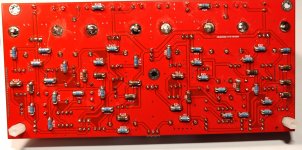
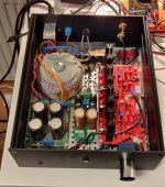
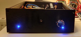
Just following up on my build. It's an amplifier with one input and no pre-out. I considered board size to be my priority thus MELF resistors and double sided soldering. However the "smallest" chassis I could fit it all in is Galxy GX288. That's not small by all means. Amp runs on D grade 2SJ74/2SK170 pairs matched @11.28mA. My ears love how it sounds so far, but to be honest with you, I don't like this build...
First of all, I must upgrade PS to what's on Jeff's schematic. I have 2x18V transformer with LM317/337 regulator following 4x10mF CRC filters supplying +/-22.8V. I presume that this limits amp's potential in terms of SQ. Second thing is that populated board looks more like a prototype than a finished build. It also has few layout inconveniences that I'd like fix. Third and most important, I still have two matched pairs of 2SJ313/2SK2013 left from my F5 build. I kept them specifically on an occasion of building HP amp. It looks like this one is one of the best there is, so no need to wait any longer. Circuit will have to be updated to deliver lower bias voltage, but that's it.
In terms of how the circuit behaves, it is really important to supply stable voltage to the amplifier as it has to thermally stabilise every time it's turned on. Thermal stabilisation takes some 30 minutes for the output offset to drop to 2mV (with no opamps in the feedback) and additional 30min for bias current to drop to 100mA per mosfet and offset to drop to 0. So just about an hour or so all together, just like it was mentioned in one of articles about HPA-1 🙂. I believe that this process depends on the volume of the chassis to an extent, but it could not be compromised too much as most toroidal transformers specs call out 40 deg C as max operating temperature. I have 37 inside around where the trafo is mounted, so just about right. Anyway, when the amp thermally stabilises, it really is stable. I have not observed any drift in terms of output offset or bias current other than one caused by differences in ambient temperature. I believe that this amp will have to be fine tuned differently for 30 deg C of outside temperature than for 20 C.
Heat sinks are important. I had too small ones and had to de-solderer and exchange them for bigger ones. Painful work. They are 8K/W now and they keep mosfet surfaces below 50 degrees.
So in the end I sort of like this build in a way, as an experimental one: a step towards understanding circuit behaviour and getting ready for final build with Toshibas. I'm listening to it now, it sounds great.
Attachments

Last edited:
Nicely done, Piotr!
I have a bunch of 2SK2013/2SJ313s if the smoke gets out of any of yours. I haven't matched them yet, but I think I have 30 2SJ313s and 40 2SK2013s, so they should pair off well.
Cheers,
Jeff.
I have a bunch of 2SK2013/2SJ313s if the smoke gets out of any of yours. I haven't matched them yet, but I think I have 30 2SJ313s and 40 2SK2013s, so they should pair off well.
Cheers,
Jeff.
Piotr,
Nice build! If you are not using the servo matching the jfets and mirror transistors may help dc offset, but I highly recommend you use the servo.
Bigger heatsinks help I would suggest the next size up and increasing the bias slightly. Keep the temp on the heatsink below 50 deg. C.
You might have given me some ideas for my next project.🙂
Cheers,
Jam
Last edited:
Thanks for the Gerbers, Jeff. The KiCAD PCB file was there. Is there any chance of sharing the KiCAD schematic? There's a PDF of the schematic but I didn't see a KiCAD file.
@hirscwi, I've attached the Kicad project.
This might be a little tricky as I use a development version of Kicad, so some of them might not open depending on what version you're using.
I you have issues, let me know what they are and I'll see about back-dating the files....
This might be a little tricky as I use a development version of Kicad, so some of them might not open depending on what version you're using.
I you have issues, let me know what they are and I'll see about back-dating the files....
Attachments
Looks like I can open it with only a couple modifications needed.@hirscwi, I've attached the Kicad project.
This might be a little tricky as I use a development version of Kicad, so some of them might not open depending on what version you're using.
I you have issues, let me know what they are and I'll see about back-dating the files....
Should be a fun project. I just built the WHAMMY headphone amp and the ACP+. Both are great and I suspect this will be also. Thanks for all your efforts n this project.
I don't seem to be able to get 2SD2081 and 2SB1259 from Mouser or DigiKey. Any reasonable substitutes or other sources I should check
Available at Digikey.
But at a hfe of ~200 at 100mA, they are not being used at their optimal, IMHO.
Patrick
But at a hfe of ~200 at 100mA, they are not being used at their optimal, IMHO.
Patrick
When i look at Digikey, the 2081 appears to be out of stock until May. Maybe they have them in Europe but I can't access them? Any substitutes?
2SD2081 / 2SD2014
2SB1259 / 2SB1257
Thank you for this information.
Jeff,
How well you ended up matching hfe of npn and pnp current mirrors?
I mean between different sexes.
How well you ended up matching hfe of npn and pnp current mirrors?
I mean between different sexes.
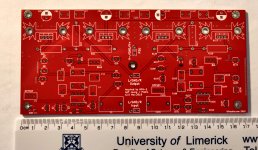
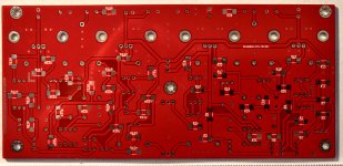
Here's my effort at a layout 🙂. I haven't included the pre-out option as I don't need it. Board size is 185 x 140mm.
I've added optional voltage regulators if op amps needing less than +-24V are used.

I've added optional voltage regulators if op amps needing less than +-24V are used.
Nice one, DontHertzMe!
One suggestion: consider putting your bias spreaders closer to the heatsinks & power resistors. I suspect the topology isn't particularly susceptible to thermal runaway, but....
Cheers,
Jeff.
One suggestion: consider putting your bias spreaders closer to the heatsinks & power resistors. I suspect the topology isn't particularly susceptible to thermal runaway, but....
Cheers,
Jeff.
One suggestion: consider putting your bias spreaders closer to the heatsinks & power resistors. I suspect the topology isn't particularly susceptible to thermal runaway, but....
Good point! Thank you for the heads up.
Also, what do you think of BC560 / BC550 instead of 992 / 1845? I have hundreds of them 😀
As I understand it the major advantage of the 992/1845 over the 550/560 is voltage (which isn't needed here). Do you have 'B' or 'C' hFE classification?
As I understand it the major advantage of the 992/1845 over the 550/560 is voltage (which isn't needed here). Do you have 'B' or 'C' hFE classification?
I've got A, B and C
- Home
- Amplifiers
- Pass Labs
- Pass HPA-1, what do we know?