Sorry for the delay here, didn't realize I was going to be asked a question.
right now dual mono
2x5600uf @ 100v 1R-25Watts heatsinked, 3x 15,000 @ 63v
I run a 40v-0-40v @ 370VA tranny on it.
Tea-bag,
how are you operating at such low voltages? Are you using bulbs or a CCS?
Thanks! I've recently dropped the supply to about 70V. Using two 200W bulbs in parallel to get about 2A bias.
I'm trying to fudge a CCS using the same IXTH part. I'm trying to simulate a voltage divider arrangement between the source and ground to bias the CCS fet. No luck so far.
Anybody done this yet?
I'm trying to fudge a CCS using the same IXTH part. I'm trying to simulate a voltage divider arrangement between the source and ground to bias the CCS fet. No luck so far.
Anybody done this yet?
I think its more a source degeneration resistor than drain resistor for the gain FET. See the aleph current source.. this one is similar but slightly simpler because of the IXTH characteristics. I would start with 0.5 ohms on the source resistor.
With the arrangement in Papa's schematic above, you can probably do away with the potentiometer arrangement in the original Delite used for setting the drain voltage.
Anyway, I'll be building this soon and will report... excited, I am.
With the arrangement in Papa's schematic above, you can probably do away with the potentiometer arrangement in the original Delite used for setting the drain voltage.
Anyway, I'll be building this soon and will report... excited, I am.
Last edited:
Does this mean another article will be published?
 I certainly hope so! 😉
 Maybe a concise update or something in the newsletter so as not to distract the Master too much..
It works for me . Not sure how properly tho . Anyway the gain increases quite a bit it seems, and virtually I prefere the light bulb version for that . 😀
More details stefano..... and even some pics?
Fran
oh , just tried the CCS example posted before ...and my Delite is just a piece of Wood , bigg transformer , bigg capacitors , a couple of precision resistors and 4 heatsinks 🙂
Hi Mr Pass,
Some questions to ask.
1)Any completed cicurit diagram ?
2)what is the value for all resistors ?
3)using same FET ( i am using D2 ,can use the same FET ? )
4)the V+ need to drop ?
Thanks
Hi Mr Pass,
Some questions to ask.
1)Any completed cicurit diagram ?
2)what is the value for all resistors ?
3)using same FET ( i am using D2 ,can use the same FET ? )
4)the V+ need to drop ?
Thanks
I can take a swipe at this.
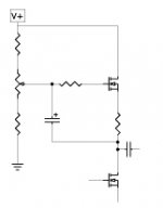
1) The bottom part below the CCS looks about the same as the Delite version 2. The drain voltage and current can be set by the voltage divider arrangement in the CCS. Just replace the bulbs with the CCS.
2) I would start with 1500 ohms for the drain to gate and gate to ground resistors. The pot could be 10k.
The source resistor can be 0.5 ohms and the gate stopper can be 220 ohms.
3) I think Papa replied for the same FET, i.e. IXTH20N50D.
4) I would start with 30V. You can adjust the drain voltage at the bottom FET using the pot arrangement. Papa recommended 20-25V in the original Delite, so a 30V supply voltage should be enough.
I think Papa intentionally left out those values for us to find out. It is indeed more fun this way. For me, this much direction was enough to get started. Any less and I probably would not be able to progress, any more and I would not learn anything 🙂
I can take a swipe at this.
1) The bottom part below the CCS looks about the same as the Delite version 2. The drain voltage and current can be set by the voltage divider arrangement in the CCS. Just replace the bulbs with the CCS.
2) I would start with 1500 ohms for the drain to gate and gate to ground resistors. The pot could be 10k.
The source resistor can be 0.5 ohms and the gate stopper can be 220 ohms.
3) I think Papa replied for the same FET, i.e. IXTH20N50D.
4) I would start with 30V. You can adjust the drain voltage at the bottom FET using the pot arrangement. Papa recommended 20-25V in the original Delite, so a 30V supply voltage should be enough.
I think Papa intentionally left out those values for us to find out. It is indeed more fun this way. For me, this much direction was enough to get started. Any less and I probably would not be able to progress, any more and I would not learn anything 🙂
Being a current source , I think we could use an output resistor to ground from 15 to 20 ohm . That would do something for the gain . F2 style 😀
Typical is 5K pot surrounded by 10K's, 100 ohm on
the Gate, 1 ohm or so on the Source. The cap value
wants to be fairly high, maybe 1000 uF.
You can go with 0 ohm on the Source, but you'll see more
of the characteristic of the CCS transistor than you might
want.
😎
the Gate, 1 ohm or so on the Source. The cap value
wants to be fairly high, maybe 1000 uF.
You can go with 0 ohm on the Source, but you'll see more
of the characteristic of the CCS transistor than you might
want.
😎
Stefano, do you mean the source resistor ought to be more like 15-20 ohms?
No , that was meant in parallel to the speaker , but at the amplifier side before the cable .
Typical is 5K pot surrounded by 10K's, 100 ohm on
the Gate, 1 ohm or so on the Source. The cap value
wants to be fairly high, maybe 1000 uF.
You can go with 0 ohm on the Source, but you'll see more
of the characteristic of the CCS transistor than you might
want.
😎
Very nice , I thought I was going to try something with the same values .
Before I tried with 0,5 ohm on the Source .
- Home
- Amplifiers
- Pass Labs
- Pass "DeLite" Amp from BAF