very cool, thanks for the start and effort.
ive never used spice. i use multisim. dont ask me what the diffrenc is, it was a requirment for a class i took. how do you like it?
ive never used spice. i use multisim. dont ask me what the diffrenc is, it was a requirment for a class i took. how do you like it?
and if it would help I could sim the circuit and find the expected voltages at each node - would allow you to see where the fault lies.
This would be so very helpful!!
I pulled the npn and Pnp ztx's on one board and dropped fresh ones in. Nothing. Tomorrow I'll swap something else and check voltages and write 'em down for you all. I certainly don't want to give up! I'm really looking forward to getting this up and running so I can start thinking about amps 🙂
I have a spare set of matched MOSFETs (Irf610 and 9610) from eBay.. Just don't want to use em unless I must. Desoldering is a pain! Thank goodness for solder suckers
@Sakellogg - I'm a complete tyro. I started playing with LTspice because a few really interesting discussions took place around designs and I wanted to try and understand what was going on. As a self teaching tool it's been pretty good - but to answer your question, I have no frame of reference LTspice is pretty awesome (and free! FREE!) and you can do amazing stuff with it. Like feed a sim a music file, have it sim your amp playing it, and playback the wav file after the amps influence. I'd recommend it.
@FormosaWest I'll try to finish the sim tonight - hope it helps!
@FormosaWest I'll try to finish the sim tonight - hope it helps!
"I pulled the npn and Pnp ztx's on one board and dropped fresh ones in"
in the future, bad idea. best to pull and test the questionable ones.
reason is this. if you have more than one problem you can end up killing your good parts and not know it.
the ones you have used for the swap/test you posted, i would recommend marking them.
just so if they do end up bad, you don't put them back in, causing a frustrating loop.
not to say they are zapped its a "just incase"
aspringv, thats cool i didnt know it was free.
"I pulled the npn and Pnp ztx's on one board and dropped fresh ones in"
in the future, bad idea. best to pull and test the questionable ones.
reason is this. if you have more than one problem you can end up killing your good parts and not know it.
the ones you have used for the swap/test you posted, i would recommend marking them.
just so if they do end up bad, you don't put them back in, causing a frustrating loop.
not to say they are zapped its a "just incase"
aspringv, thats cool i didnt know it was free.
Thanks for the great insight sakellogg. I see what you mean. I hadn't thought of that. In the future ill be more cautious.
Im going to try and do some measurement of voltages on the boards. I really hope i can find the problem soon.
Now it's working properly
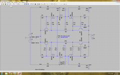
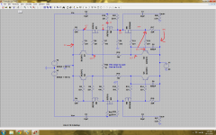
I reckon thats close enough. The mosfets in the sim are as close as I could find to 610/9610's and the circuit seems to work as expected. The numbering of components is completely different, so you'll need to work out which component is which by yourself. However if you look at the schematic I tried to draw it out roughly equivalent to the veteran schematic so it should be easy enough to work out.
If you sim the circuit (the wee running man symbol) and then mouse around the nodes, you'll get the voltage you should expect at each point.
Hope that helps!
Attachments
Thanks for the hand!
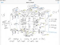
Ive probed some voltages for you to take a look at. Id love your thoughts. I hope you can see the picture. Im using a mac, so ill have to do some research about spice. Ive never used software like this since im very new to this hobby!
Ive probed some voltages for you to take a look at. Id love your thoughts. I hope you can see the picture. Im using a mac, so ill have to do some research about spice. Ive never used software like this since im very new to this hobby!
Attachments
Ive probed some voltages for you to take a look at. Id love your thoughts. I hope you can see the picture. Im using a mac, so ill have to do some research about spice. Ive never used software like this since im very new to this hobby!
cool thankyou.
however, could you post the Drain to Source Vdc for each fet also? should be pin 2 and 3 or the tab and 3.
also, on the ztx's the collector to emitior Vdc too.
and here is why. ill do everything i can do to help but, im not the smartest dodo on the fourm, thats zenmod.
i need those readings in addtion to what you gave to start the trouble shooting and math i know. not to say someone more experenced wont see somthing i wont.
i dont mean to be a pain, just how my brain works.
as far as a sim program..... i use multisim and like it. i thought until this thread spice and what i had where the same....kinda. but as far as mac, i dont know.
worth finding out. i love my sims. helps the thinking.
OK, Sorry, I probably should have specified the preferred test procedure. Keep in mind I'm no expert either!
As a top line what we're looking for is the operating voltages of the pins of the mosfets. From this we should be able to work out the rest of what we might need to know.
First up, we don't need a signal initially - we're interested in the DC voltages at the pins. Ground the inputs - I usually just clip a clip lead between the input(s) and signal ground. Then get the DC voltage at each mosfet pin (be careful! don't bridge across the pins with the probe) and just give us those values.
Hope this helps!
Edit - sorry again, realized the pic was unclear, will remove and repost
Edit2 - fixed!
Attachments
Last edited:
cool thankyou.
however, could you post the Drain to Source Vdc for each fet also? should be pin 2 and 3 or the tab and 3.
also, on the ztx's the collector to emitior Vdc too.
i dont mean to be a pain, just how my brain works.
Hahah! not a pain at all.. Youre a great help and i value your experience. Im actually quite illiterate in electronics, but as a critical thinker and open minded life-long learner i can only hope to accomplish anything with the help of generous assistance from fellow music lovers such as your self.
Ill post the D to S vdc values tonight. 🙂
OK, Sorry, I probably should have specified the preferred test procedure. Keep in mind I'm no expert either!
As a top line what we're looking for is the operating voltages of the pins of the mosfets. From this we should be able to work out the rest of what we might need to know.
First up, we don't need a signal initially - we're interested in the DC voltages at the pins. Ground the inputs - I usually just clip a clip lead between the input(s) and signal ground. Then get the DC voltage at each mosfet pin (be careful! don't bridge across the pins with the probe) and just give us those values.
Hope this helps!
Edit - sorry again, realized the pic was unclear, will remove and repost
Edit2 - fixed!
Thank you! Im definatly not getting the same values. Th epower supply is producing 60v but when its connected to the board it measures to 1.5v.
Ill have the specified readings tonight. Thanks for the tip about grounding the input temporarilly. Ill take the d-s readings... Just to be sure i do it right.. One probe to drain, the other to source and report positive values?
Thanks for being patient with my illiteracy in EE and circuitry! Im learning tonnes every day.
"Just to be sure i do it right.. One probe to drain, the other to source and report positive values?"
yes please.
just a thought.
i try to avoid having the probes so close together when i test these. legs are so close that Ive slipped and zapped things before.
remember the tab on the fets are also the same as the drain pin. so one probe on Source leg and one on the tab will work too.
yes please.
just a thought.
i try to avoid having the probes so close together when i test these. legs are so close that Ive slipped and zapped things before.
remember the tab on the fets are also the same as the drain pin. so one probe on Source leg and one on the tab will work too.
Hi,
I just did a quick re-read of the thread and had a look at your gallery posts (nice btw), and I might just generally suggest a few things to check.
Before I start, I might just say that I'm both an amateur at this and tend to overthink problems, so I tend to try and eliminate as many other potential problems first...
Given you had a problem earlier with your power supply (and you appear to be reading 1.5V where you should be seeing 60V) I'd test your power supply(s) first. The p1.7 should draw about 70mA (I think - this data is from the sim), so a 1K resistor would be a close dummy load. Note that this is nearly 5W of dissipation through the resistor, so you'll want a fairly hefty resistor. The power supply should handle this fine and you should see 60V across the resistor. If not, the problem is 'upstream' of the P1.7 boards (ie psu boards, power connector, dodgy connection, transformers, switches etc).
After that, check the mosfets on the p1.7 for electrical isolation. check to see that the tabs of the mosfets are electrically isolated from the heatsink you have on them. Probing for resistance between tab and heatsink should show an open circuit.
Shorts and bad solders? Have a good look at your soldering for any inadvertent shorts/dry joins. I found a lot of the pads on vets boards were pretty close together under the mosfets and I bridged a few of em when I first soldered them up.
If all this seems ok, then we can look for component failures...
D-S values in vdc:
Irf 610
T2 no reading
T1 no reading
T8 no reading
T9 no reading
IRF 9610
T3 -0.510v
T10 -0.510v
ZTX450. C-E
No reading
No reading
ZTX550. C-E
No reading
No reading
When boards are powered off voltage is 60.0v, and 1.53v when powered on. Where is the power going?
The matched mosfets i bought off of a diyaudio forum member.. Who didnt ship them for 3 months and claimed in some correspondances to have sent them and in others to have not yet sent them. It took so long to get them that i ordered some more from ebay (china) and have spares matched to an unknown value. In both cases, they were shipped in normal bags, not static protected bags.
The ztxs are from digikey / mouser and are unmatched.
Soldering looks okay. I had examined them under magnification prior to mounding them in the box. Indeed, The pads are very close. In some places the solder -IS- bridged, but only where the tracks are directly connecting the two points already. Bridged solder only occured in these places because heating the pads also heated the track and neighboring pins such that the solder flowed towards the heat. I tried to minimize it, and can remove the excess, but am uncertain if it will make a difference.
Removing the bridged solder, confirmed that there is track beneath and continuity... So probably not it.. But good critical thinking.
I replaced the 1000uf 100v polar nichicon kw(m) caps with new ones and replaced the ztx 450 and ztx550 with 451 and 551. There are new ones in the board now too, cause i had a spare pair of each.
I figured 451 and 551 were ok replacements for 450 and 550 and were what i had ordered.
Very strange that the power supply is good until the boards are powered up. The power supply is also good when totally disconnected from the audio unit and examined in isolation. The irf610 in the one power supply channel was the culprit in that case and (likely) due to accidentally wiring the boards in reverse... Which may have also fried some parts on these boards...
Im wondering if the individual who sold me the irf610 and 9610 sold me fried ones or fakes
Last edited:
Dummy load on power supply of 1.2k 3w resistor yields a drop from 60.0v to 0.765v !
What!?
Im going to try something.
I have a relay controlled bleeding resistor across the powerpower terminals in the power supply to drain the power supply caps when the power supply (relay) is powered off and separated from the box., and it is removed during powered on state. I added these to keep me from electrocuting myself during work and its been seemingly effective... Im going to pull them and see, though i dont think they are the issue because i had the, not connected for much of the earliest testing...
The transformers are r-cores, 120v to 60v / 1A 50va type, one per channel (dual mono), and 120v to 9v / 7.5va for aux power.
Removing the relay triggered bleeding resistors resulting in no change... Boards cause 60v to drop to 1.5.
I included the bleeding resistors because i anticipated that i would be using a power switch / relays to control and coordinate dc power delivery to each of the components (attenuator, ource relays, boarsds
In power off/ standby, the boards are disconnected from the 60vdc, tand he boards cannot discharge the power supply caps.
The power to boards is controlled by dc relays running on the aux supply and power switch, which control the dc power delivery to the boards.
The ac power is switched by an x-capped dpdt at the power IEC .. Standard fare..
Must deduce, Bleeders not a problem...
Still charges up to 60v slowly (up to about 58-59 in about 10 sec and 60 in a minute.
Last edited:
Nice! Looks like you're on your way to solving it alright.
With regards to parts, my board is almost entirely populated with ebaY components and I've only seen a few fakes so far, and these have been for unobtanium parts or for large power BJT's. I tend to have more issues between my ears than I do with parts 🙂 For fun I've ordered a few probable fakes and enjoyed the process of trying to work out what the hell they were.
Anywho, don't sweat the matching or providence of parts for now - and I don't believe the ZTX parts are needing matched anyway (FWIW I'm using BC550's and I believe any small signal transistor will do), and irf610's are cheap enough to not bother faking.
Nice work! I hope you get to the bottom of it.
Again FWIW, matching parts is pretty easy, and it's handy to have spares when this sort of thing happens, so buy em by the 25 or 50 and save a buck or two... And then you have ammunition for the next project!
At power off, there is 0.61ma current draw. at power on there is 0.00ma current draw..
This is the same with a dummy load on the power supply.
Im so confused.
Im desperately hoping its the mosfets, but i dont understand circuitry like you folks..
This is the same with a dummy load on the power supply.
Im so confused.
Im desperately hoping its the mosfets, but i dont understand circuitry like you folks..
Last edited:
- Home
- Amplifiers
- Pass Labs
- Pass Aleph P 1.7 preamp builders thread