Re: Re: My PP version
It's your choice 😱
But I must confess I've a psycotic aversion again bypass capacitors, specially on lo Z circuit 😀
The best bypass I know is a SHORT piece of wire !
Yves.
planet10 said:
And i was just wondering what to do with the ECL86 PP donor amp pictured 🙂 It's a Viking with tubes made in Holland.
Cathode bias would be nicer... even better Class A with a CCS on the output cathodes ....
dave
It's your choice 😱
But I must confess I've a psycotic aversion again bypass capacitors, specially on lo Z circuit 😀
The best bypass I know is a SHORT piece of wire !
Yves.
Andrewbee,
just remind me what schematics are we talking about -- you mention the KT88, so I believe it is about the RH88(6550). If that is so, just a short explanation -- but you can always e-mail me for details (get the address on my site!).
I recall having published the RH88 amp in its DC form, for extra power, as a scoop. Actually, I have not tried that one yet, among other things, because of the flue. If you are going to build the RH88, you should do it in it's regular form, which has not yet been published.
Yes, both versions we are discussing are in triode mode! Therefore, anode and g2 are interconnected by a 1k resistor directly on the socket.
Georgehifi,
I already said I was down with the flu... of course I am aware that the delay delays the B+ high voltage, not the heaters!
And, of course I am aware that there is a "tertiary winding" on the transformer, used for feedback -- only I do not think that this form of "partial feedback" (?) applies to the purpose and theme of the thread -- instead of discussing alternatives and building some, most people are showing up with their designs, which in your case are far from the subject, although being interesting in themselves.
When I say "overly complicated" I am not meaning that there should be something less in the signal path (although maybe it might), but that there are too may parts in the amp, that the schematic is complicated and not simple... etc.
By the way, if you were not using a passive preamp (sic -- call that one a box with a pot and a selector) you might do without one of the stages... and use your cables better (lower and more constant impedance, etc.).
Generally, what I dislike is when people come out grasping at little typos and similia, and assuming that whoever wrote has not tought about it enough, or does not have enough knowledge to understand... or whatever. I sincerely believe my comments were in order: your amp is 1) complicated 2) uses a lot of SS stuff. But it is your amp, and you can be proud of it, especially if you have built it yourself, and even more, if you have "thought it out" by yourself.
Enough said.
Regards to all,
Aleksandar
Re: Re: My PP version
p10, this is a perfect candidate for my trick of series/paralleled red LEDs as cathode load. Figure 30mA max per series string, 1.7V per LED in the string. I've got this running in one channel of a pp EL84 amp and it sounds like it's got twice the power (superior overload recovery).
planet10 said:
And i was just wondering what to do with the ECL86 PP donor amp pictured 🙂 It's a Viking with tubes made in Holland.
Cathode bias would be nicer... even better Class A with a CCS on the output cathodes (i happen to have a pr of 210VAC trafos that would suit a set of monobloks)
p10, this is a perfect candidate for my trick of series/paralleled red LEDs as cathode load. Figure 30mA max per series string, 1.7V per LED in the string. I've got this running in one channel of a pp EL84 amp and it sounds like it's got twice the power (superior overload recovery).
Re: Re: Re: My PP version
Hi SY !
Looks good to me, and satisfies my " no bypass paranoia " !!
This is a "CVS" : Constant Voltage Source 😉 Isn't it ?
AFAIK, differents colors have different knee voltages.
Regards, Yves.
Hi SY !
SY said:
p10, this is a perfect candidate for my trick of series/paralleled red LEDs as cathode load. Figure 30mA max per series string, 1.7V per LED in the string. I've got this running in one channel of a pp EL84 amp and it sounds like it's got twice the power (superior overload recovery).
Looks good to me, and satisfies my " no bypass paranoia " !!
This is a "CVS" : Constant Voltage Source 😉 Isn't it ?
AFAIK, differents colors have different knee voltages.
Regards, Yves.
First, let me say that if I were you, I'd be up in Ampuis this weekend!
It's pretty close to a CVS. Each red LED has an AC impedance of about 4-5 ohms. In a series/parallel array biasing the tubes' cathodes to roughly 10.5V, each series string would be predicted to have a 30 ohm impedance. Put 5 series strings in parallel and the impedance is less than the current-monitoring resistor that one normally sees in output tube cathode circuits.
Since the LEDs are operated in a forward bias mode, recovery from overload is instantaneous. No RC time constants.
I only wish this were practical for bigger tubes...
In any case, I haven't done impedance measurements on different color LEDs, but conveniently, Morgan Jones has. He found that cheap red LEDs were the best for cathode biasing.
I found that NiCad cells are best for biasing.
hehe,you can even have a charger and listening device in one 😉
hehe,you can even have a charger and listening device in one 😉
What's recovery time like for a battery bias? I've used it in grid circuits but never in cathodes.
Back when I was using LEDs for cathode bias I did some testing of the voltage and impedance of various color LEDs. Basic rule is true red has the sharpest knee and lowest impedance. As the colors go towards blue both the voltage and impedance is higher. Even the high effiency red (a little more orange tint to them) LEDs have a higher impedance. I did not test any IR LEDs so I don't know how they fit in the equation.
A friend and I did some listening tests with LEDs, Nicads, and unbypassed Vishay wire wound resistors. The listening tests were done on my 26 line stage with the battery biased CCS for the plate load.
In this test the unbypassed wirewound resistor came out on top with the LEDs second and the Nicad batterys coming in last. Compared to the wirewound resistor the LEDs had a very slightly grainy sound. The Nicad batteries sounded slugish and veiled compared to either the wirewound resistor or LEDs. The sound of the Nicad made me think of a high quality electrolytic capacitor. When you think about it both a battery and electrolytic cap have chemical processes going on during operation.
All the info above applied to a CCS loaded triode with the output taken off the MU output of the CCS so there wasn't really any drawbacks to the unbypassed resistor. Another way of looking at the circuit is a resistor biased triode with a CCS plate load is running in fixed bias.
Gary
Gary, the advantage of using them the way I do (cathode bias in a p-p output stage) is that any minor nonlinearity is common mode, hence knocked down by another couple of orders of magnitude.
Hi Sy,
Your correct about the PP circuit. Also, the noise from the LEDs is common mode so should not show up in the output as grainy sound.
When I was messing around with LED bias it was with single ended circuits so my brain was still in SE mode.
After developing some high quality PP amps the single ended phase is fully over. Just don't care for the colored sound of SE.
Gary
Gary P said:
After developing some high quality PP amps the single ended phase is fully over. Just don't care for the colored sound of SE.
Gary
It is good that you have left the Dark Side.
😀
Partial Feedback issues
Hi there,
Some help on this matter wanted:
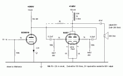
I red John Broskies article covering partial feedback http://www.tubecad.com/march2001 and tried it on a SE OTL feeding an 800 Ohms Philips speaker. (AD3800AM)
Gives great open sound, within it's limitations (mainly the speaker)
It works, but.... I get a reasonable output only untill the Powertube 6AS7 starts to draw grid current. The partial feedback seems not to help there. Also the value of the feedbackresistor is limited, because it is parallel with Millercapacitance of the powertube and so limites bandwidth. In my case about 47k for a max of 100khz. Not bad anyway.
To me it seems that there is a substantial difference in the feedback mechanism if the driver has it's own Ra instead of using the feedbackresistor as Ra.... In the first case, as I have used it, it looks like the driver just can't supply enough current for both it's own Ra and Rfeedback. so I think this cannot be a I to V convertor as JB described. Please correct me if I am wrong
Now I was thinking: Would adding a CF overcome these issues?
I've made up a drawing, to make my point. I used JB's drawings as a starting point. (3 Attachments)
Any comments are welcome, as i'm not trying to reinvent the wheel. 😉
Ok, thanks for reading this longish post and I hope to have given some interesting read.
Mark
PS. How can I put drawings in a reply iso attachement? Would be convenient to know
Can't do multiple attachments either 😕
Hi there,
Some help on this matter wanted:
I red John Broskies article covering partial feedback http://www.tubecad.com/march2001 and tried it on a SE OTL feeding an 800 Ohms Philips speaker. (AD3800AM)
Gives great open sound, within it's limitations (mainly the speaker)
It works, but.... I get a reasonable output only untill the Powertube 6AS7 starts to draw grid current. The partial feedback seems not to help there. Also the value of the feedbackresistor is limited, because it is parallel with Millercapacitance of the powertube and so limites bandwidth. In my case about 47k for a max of 100khz. Not bad anyway.
To me it seems that there is a substantial difference in the feedback mechanism if the driver has it's own Ra instead of using the feedbackresistor as Ra.... In the first case, as I have used it, it looks like the driver just can't supply enough current for both it's own Ra and Rfeedback. so I think this cannot be a I to V convertor as JB described. Please correct me if I am wrong
Now I was thinking: Would adding a CF overcome these issues?
I've made up a drawing, to make my point. I used JB's drawings as a starting point. (3 Attachments)
Any comments are welcome, as i'm not trying to reinvent the wheel. 😉
Ok, thanks for reading this longish post and I hope to have given some interesting read.
Mark
PS. How can I put drawings in a reply iso attachement? Would be convenient to know
Can't do multiple attachments either 😕
Attachments
Hi Mark
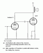
I've played too with various implementations of this design with more or less success.
Interresting results where obtained in using a somewhat classic SRPP configuration for the driver, feeding the grid of the output stage from the upper cathode and returning the feedback resistor to the plate of the lower anode.
The two cathode resistors of this SRPP may be made unequal, since the FB resistor adds current in the lower portion alone.
The basic problem is pointed by JB, but he stops his paper before giving a practical solution.
That is: The plate of the output tube goes down, say near to its saturation voltage, on positive going alternance of its grid drive. At this point the driver must still pass some current altought its instantaneous supply voltage is so low.
IMHO, this could be solved by returning the cathode of the driver to a negative supply (or rising the cathode of the output tube, wich is not easier).
For now, it's what I plan to check using a penthode as driver and a -100v auxiliary supply.
And ... euh ... the huge voltage drive needed by the 6AS7 complicates the problem more than a lot but I understand this choice is to cope with your speaker.
I beleive that the higest the Mu, the better for the power tube.
Regards, Yves.
SY said:What's recovery time like for a battery bias? I've used it in grid circuits but never in cathodes.
what you mean with "recovery time" ?
Fun With Feedback
This is George of www.artsrestoration.com. If you look on the site, you will see some of the McIntosh amps I have done. These amp uses both cross-coupled positive and negative feedback in several places as well as the open loop feedback.
Some of the greats like Fisher used complex push-pull feedback from output back to the drivers. Plate of output tube to grid/kathode of driver triodes, as well as open loop. Then the open loop is less and less compression.
If you take a resistor from the plate of the output tube to the grid through a cap, you will lower the gain of the tube and the gain of the output stage.
I use a small amount, 15 to 75 ohms, metal oxide 5W, in the kathode of the output tube as tubes are real sensitive to any kathode feedback. Then the gain of the tube falls off a little, it gets quiet, it is more stable, and the grid impedance is higher so the drive current needed on transients is less..
Look at a MC-75 or MC-30 circuit or a Fisher amp circuit for some feedback fun. I just fineshed a 275 that had a bad feedback coil to the 12at7 so I had to re-design the circuit around it...
There was also a coil o the output tranny that was neg feedback to the driver or even 1st gain stage. They used to have other windings in the trannies but cheaped up in later years..
EL84's work great with about 33 ohm dry resistance in the kathode. They queit up and tighten up, better clarity etc...😎
WHAT IS THIS?
This morning, when I logged in... for a moment I was not sure whether I have chosen the wrong shortcut -- but it said, above on the screen "Partial Feedback Amplifiers"!
Vikings, red leds, dark side being SE amps... this has nothing to do with the thread. I could invite a couple of buddies to join me here for a chat on the latest serbian basketball league results, or something like that, I think it's the equivalent.
Count me out guys, this is a loss of time.
Regards to all,
Aleksandar
Re: Fun With Feedback
dry resistance??
dave
FranStar said:EL84's work great with about 33 ohm dry resistance in the kathode
dry resistance??
dave
Mark,
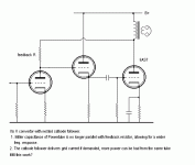
I think your schematic showing a cathode follower between the driver and the output valve, and a feedback loop from the anode of the output valve to the grid of the cathode follower would work. It's the only solution to the conflicting requirements of low output impedance for wide frequency response and high output impedance for high levels of local feedback I've seen. But now we're wrapping feedback around two stages instead of one, so we have to be careful about possible phase shifts and things because we have more components in the feedback loop.
Alex,
I don't see where this is coming from... The red LEDs aren't strictly to do with local feedback, but are an alternative form of cathode bias. Anyway a little bit of OT stuff can be constructive - remember what happened to the EL84 SE Design Reccomendations thread?
- Status
- Not open for further replies.
- Home
- Amplifiers
- Tubes / Valves
- Partial Feedback Amplifiers