Hi Frans, i got a couple of spare k170bl to swap out . Would 390R be ok? I noted that the simulation use 360R and you recommended 330R.If you want to replace the PSU J310's by 2SK170's then you need to replace the Rgs (R108/208 3.3k) with an resistors of 360 Ohm as shown in the schema that is with the graph. #1772 http://www.diyaudio.com/forums/analogue-source/218625-paradise-builders-178.html#post3419918
This 'upgrade' is only for the PSU J310's not for the RIAA J310's.
The preferred NJF to use is the J113 (not the 2SK170, but any NJF needing a Rgs of 1k or less is perfect, any NJF needing a Rgs of 2k or less is good, any NJF needing a Rgs of 3k or less is usable (but needs measurement to be sure that it is in spec)).
Quan
Are there two versions of the Paradise PCB-s ?I see input trimmer pots on some pictures. What is wrong with Paradise grounding configuration? Star earth single side PCB better than groundplane approach?
Hi Frans, i got a couple of spare k170bl to swap out . Would 390R be ok? I noted that the simulation use 360R and you recommended 330R.
Quan
You can solder those on top of existing ones 3K3 (?) and end up with about 348 Hom's
Are there two versions of the Paradise PCB-s ?I see input trimmer pots on some pictures. What is wrong with Paradise grounding configuration? Star earth single side PCB better than groundplane approach?
The beta boards R2 did not have the trimmer and same foot prints where smaller.
R3 has trimmer and foot print now make it easier to weld the J fet in place.
You can solder those on top of existing ones 3K3 (?) and end up with about 348 Hom's
Thanks Sandro
Thanks Frans! I have some 327 around 330 and 337 around 460. I'm going to assume no matching is required. 🙂
Hi Ungie,
one of the wise guys told us, some posts ago,
the input doublequad should be rather high (~450?)
those mediocres just have to be matched as long as
they reach >200.
Right ?
Matching and mating not needed 🙂 https://www.youtube.com/watch?feature=player_detailpage&v=9NbFfYHD8rY
Hi Frans, i got a couple of spare k170bl to swap out . Would 390R be ok? I noted that the simulation use 360R and you recommended 330R.
Quan
If you have a exact spice model for this (instance of) NJF then I can tell you 🙂 (IOW I do not have a K170BL model). The easy way out is, mount a 1K trimmer as Rgs mount a battery of 9Volt Vds and add a mA meter in series with the battery. Then turn the knob until 1mA current flow is accomplished. Now all that rest to do is, measure the value of the trimmer that has been set and apply that value +-10% to the PCB 🙂
These are the most important/relevant messages regarding PSU and Pre-Reg.
- Mpp #4375 PSU-pre-regulator.
- Mpp #4610 V2 Schemas UPS and Amp.
- Mpp #6506 CCS fine-tuning.
- Mpp #6462 PSU with my notes.
- Mpp #6809 Do not try to feed the CVS of the CCS of the shunt with a regulated power supply.
- Mpp #7127 More about transformer selection.
- Mpp #7635 Single and dual transformer wiring (also corrected drawing) (See also #7733).
- Mpp #7733 Grounding (PSU, RIAA and Player).
- Mpp #7810 35V PSU for the CroMagnon.
- Mpp #7830 The PSU explained.
- Mpp #8386 My resistor recommendation’s.
- My Paradise #56 PSU Noise.
- PradiseBuilders #13 Schema's and assembly guide.
- PradiseBuilders #155 Vdc input voltage minimum simulated.
- PradiseBuilders #970 PSU oscillates; posible solutions?
- PradiseBuilders #983 Compensating the PSU for oscillations.
- PradiseBuilders #1173 Fixing oscillations (up to #1182).
- PradiseBuilders #1322 Fuse 🙂.
- PradiseBuilders #1387 Updated Paradise R3 assembly guide (Also German).
- PradiseBuilders #1403 Capacitors bad vs good.
- PradiseBuilders #1593 PSU Power Transistor selection.
- PradiseBuilders #1644 PSU Output Impedance.
- PradiseBuilders #1680 PSU Power Supply Suppression Ratio(PSSR).
- PradiseBuilders #1772 NJF selection for the PSU.
- PradiseBuilders #1887 Empirical NJF Rgs determination.
Last edited:
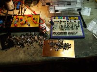
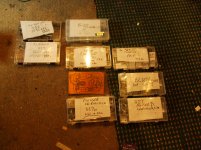
I know this has probably been asked before, but how close do the groupings of NPN and PNP transistors need to match each other in the input stage? Most of my NPNs are in the range of 460-500 and the PNPs are from 360-420. Could NPNs with 460 and PNPs of 400 be used together? I think I'm probably looking at yet another expensive Digikey order (first was to fix the group buy parts issues) for a batch of Fairchild PNPs. 🙁
I know this has probably been asked before, but how close do the groupings of NPN and PNP transistors need to match each other in the input stage? Most of my NPNs are in the range of 460-500 and the PNPs are from 360-420. Could NPNs with 460 and PNPs of 400 be used together? I think I'm probably looking at yet another expensive Digikey order (first was to fix the group buy parts issues) for a batch of Fairchild PNPs. 🙁
The guide suggest 10percent or better to reduce offset thus it is a bit over the recommended values.
K170 at 10.5 mA seems way too high.... please try with 7mA
Measure J310 Idss and choose the highest you can get.
Good evening lads
Hi Ricardo
I have changed out Q 90,91, 92 to the highst value I had 36,5 mA
and Q99 to the lowest I had 8,2 mA, no difference again. I have
double checked everything again and again. No clue whats going poorly.
Werner
Found this
MODEL 2sk170 NJF
+ VTO=-5.211e-001 BETA=3.683e-002 LAMBDA=4.829e-003
+ IS=1.000e-009, RD=0.000e+000 RS=0.000e+000
+ CGS=5.647e-011 CGD=2.562e-011
+ PB=4.860e+000 FC=0.5
http://www.diyaudio.com/forums/pass-labs/1977-2sk170-389-spice-models.html
and this
In Reply to: 2SK170 Spice Model posted by TonyB on July 16, 2003 at 05:50:05:
Hi TonyB,
.model 2sk170 NJF
+ Beta=59.86m Rs=4.151 Rd=4.151 Betatce=-.5 Lambda=1.923m
+ Vto=-.5024 Vtotc=-2.5m Cgd=20p M=.3805 Pb=.4746 Fc=.5
+ Cgs=25.48p Isr=84.77p Nr=2 Is=8.477p N=1 Xti=3 Alpha=10u Vk=100
+ Kf=111.3E-18 Af=1
Another one:
.model 2sk170 NJF
+ VTO=-5.211e-001 BETA=3.683e-002 LAMBDA=4.829e-003
+ IS=1.000e-009, RD=0.000e+000 RS=0.000e+000
+ CGS=5.647e-011 CGD=2.562e-011
+ PB=4.860e+000 FC=0.5
Pedja
Re: 2SK170 Spice Model - Pedja - Tweakers' Asylum
Brunei calling again!
Just checking something here:
I fired up the amp section some days ago, my results are:
- input offset 0 (with input R=18R) on both channels
- output offset still wandering, somewhere around max +/-30mV on both channels
No problemo it seems... it has 10 hours on power I guess to still may be settling.
Then I measured pin 6 of the servo opamp, and on one channel this is near 0 (almost perfect), while on the other channel it is correcting at -8V (DC, meaning the corrections are still max 50mVac around this 8Vdc point) ! I tried the steps in the manual, by increasing the input R to 10K (to check for input stage mismatches) and by replacing Q99 (2SK170). Both these actions gave no significant change in behavior, still quite little offset in the output but high voltage on pin6....
On the scope i see on both channels some noise, just a significant 60Hz buzzzz on both channels (both the good and the bad channel using 10K as input R). At least no oscillations or funny stuff as far as I could see.
Last edited:
Hi studiostevus, looks like your boards are fine. The offset on one board (where the opamp output voltage is -8V) is a little high but still ok. Can you please measure the voltages across the "Ext RIAA" connector on both boards?
Firstly, i have not soldered the components of the riaa circuit yet. the parts gb did not give me the required components. Not sure what this does to the measurements, but here they are.
My 'good' board shows a virtually flat line across ext riaa. However..... The 'bad' side shows this: (2Vac/Div and 0.1us/div on a 50mhz scope). Oscillations oh yes
EDIT: I REMEASURED, and it seems I have some ground-loop trouble. The above picture is taken with one channel of the scope connected to the good board, and one channel (the one shown on the picture) to the bad board. If I disconnect the other channel, the picture of the bad board gets better (still +/- 1.5V sinusoidish), but definitely not as clear as the picture above. Again, the good board doesnt display any of such behavior
My 'good' board shows a virtually flat line across ext riaa. However..... The 'bad' side shows this: (2Vac/Div and 0.1us/div on a 50mhz scope). Oscillations oh yes
An externally hosted image should be here but it was not working when we last tested it.
EDIT: I REMEASURED, and it seems I have some ground-loop trouble. The above picture is taken with one channel of the scope connected to the good board, and one channel (the one shown on the picture) to the bad board. If I disconnect the other channel, the picture of the bad board gets better (still +/- 1.5V sinusoidish), but definitely not as clear as the picture above. Again, the good board doesnt display any of such behavior
Last edited:
oh oh...... without the RIAA components, the RIAA node (which hangs between two current sources) is floating, and DC levels are "up in the air" so to speak.... you may want to put a 50k...82k resistor across "Ext RIAA" connector just for the moment, to see what happens.
These oscillations look like PSU troubles, did you put the compensation caps? (Check out the assembly guide, thats in there now)
These oscillations look like PSU troubles, did you put the compensation caps? (Check out the assembly guide, thats in there now)
Found this
MODEL 2sk170 NJF
+ VTO=-5.211e-001 BETA=3.683e-002 LAMBDA=4.829e-003
+ IS=1.000e-009, RD=0.000e+000 RS=0.000e+000
+ CGS=5.647e-011 CGD=2.562e-011
+ PB=4.860e+000 FC=0.5
http://www.diyaudio.com/forums/pass-labs/1977-2sk170-389-spice-models.html
and this
In Reply to: 2SK170 Spice Model posted by TonyB on July 16, 2003 at 05:50:05:
Hi TonyB,
.model 2sk170 NJF
+ Beta=59.86m Rs=4.151 Rd=4.151 Betatce=-.5 Lambda=1.923m
+ Vto=-.5024 Vtotc=-2.5m Cgd=20p M=.3805 Pb=.4746 Fc=.5
+ Cgs=25.48p Isr=84.77p Nr=2 Is=8.477p N=1 Xti=3 Alpha=10u Vk=100
+ Kf=111.3E-18 Af=1
Another one:
.model 2sk170 NJF
+ VTO=-5.211e-001 BETA=3.683e-002 LAMBDA=4.829e-003
+ IS=1.000e-009, RD=0.000e+000 RS=0.000e+000
+ CGS=5.647e-011 CGD=2.562e-011
+ PB=4.860e+000 FC=0.5
Pedja
Re: 2SK170 Spice Model - Pedja - Tweakers' Asylum
Both work... thanks
You are welcome
As posted those came from intraweb but still hapy to return a bit of help in my small way
As posted those came from intraweb but still hapy to return a bit of help in my small way
- Home
- Source & Line
- Analogue Source
- Paradise Builders


