I had a look at some pictures. The boards have no parts numbers, but part values and designations.
It must be possible to find two caps like this (C91, C92) - if they exist in the layout - and check for
polarity.
When running the board you may want to check for a hot component.
It must be possible to find two caps like this (C91, C92) - if they exist in the layout - and check for
polarity.
When running the board you may want to check for a hot component.
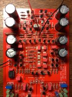
Boards are R2.
All caps have the correct polarity, no hot components.
The positive rail draws about 156mA of current, the negative (the one having issues) about 140mA. Does This point to a problem with the power regulator?
what if i would connect the regulator from the other board to see if the amp was working? If so, the problem would hen be the regulator.
Last edited:
I see that two different boards are marked R2, however somewhere I read
that the difference between R2 and R3 is marginal.
You have to find out why the neg rail shuts down (I suspect your 140 mA
is with the reduced voltage?). Please try to be as precise as possible, the
current is useless without knowing the voltage. I advised checking with a
resistive load, this is easily done.
Generally current should be about the same in both branches. If not there is
an unexpected path to ground.
I want to take the opportunity to appeal to the inventors and designers of
(all) circuits called Paradise Phono :
Reliable links to valid schematics, bill of material, board layout and build
instructions should finally be provided and good pictures added. It is always
possible to edit the first post of any thread for this purpose. As is, the
distributed documentation of this project is a discouraging mess and the
schematics are ugly.
With a resistive load of 180Ohm I had lying around the voltage stays constant at -18V. Current would then be 100mA
the 140mA was measured when connecting the Amp and the voltage dropping to around 7V
the 140mA was measured when connecting the Amp and the voltage dropping to around 7V
Another idea :
The neg rail may be current limited. Check both with 180//180 ohms.
Where can I see your supply schematic to confirm this is a valid approach ?
The neg rail may be current limited. Check both with 180//180 ohms.
Where can I see your supply schematic to confirm this is a valid approach ?

If this is true the supply is current limited to 1,25V / 8,2 ohms (LM 317 as source).
Check for 1,25 volts across the test points 201 and 202, compare to 101 and 102.
Check for 1,25 volts across the test points 201 and 202, compare to 101 and 102.
Re the picture in post 4461 you used OPA134. The current draw of this is
about 4 mA and enough to light up the 2 x 4 op amp LED strings. Sorry
I can not see the complete board.
about 4 mA and enough to light up the 2 x 4 op amp LED strings. Sorry
I can not see the complete board.
re. the photo in #4461, you need something in the Neumann position. Most people just use a wire link. Without this the riaa correction will be way off (it also provides a gnd ref. for the 11nF caps).
Not sure that is the problem, though. I’m with @as_audio — your amplifier board is drawing more current on the -ve side than the PS can supply at required voltage, and this is highly likely due to a stuffing error of some sort
Not sure that is the problem, though. I’m with @as_audio — your amplifier board is drawing more current on the -ve side than the PS can supply at required voltage, and this is highly likely due to a stuffing error of some sort
Both rails work fine.Another idea :
The neg rail may be current limited. Check both with 180//180 ohms.
Where can I see your supply schematic to confirm this is a valid approach ?
Soldered a wire link into the Neumann position. No changes.re. the photo in #4461, you need something in the Neumann position. Most people just use a wire link. Without this the riaa correction will be way off (it also provides a gnd ref. for the 11nF caps).
Not sure that is the problem, though. I’m with @as_audio — your amplifier board is drawing more current on the -ve side than the PS can supply at required voltage, and this is highly likely due to a stuffing error of some sort
Will again check resistors and the rest is there are any stuffing errors.
- Home
- Source & Line
- Analogue Source
- Paradise Builders