
Drives me nuts too.But that diagonal resistor......
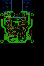
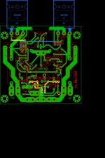
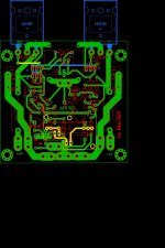
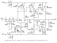
Your bias transistor q9 is best directly coupled to one of the drivers. Not just on the same heatsink. For it to do it’s job, it needs to track the junction temp of one of the drivers as close as possible. Being placed between them on the same heatsink introduces thermal lag.
It will probably work but is not ideal.
It will probably work but is not ideal.
brian92fs
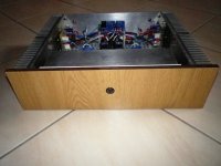
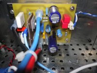
Ιt is not the first time that I make this amplifier with this transistor, Q9 it is completely free to not even touch the drivers. the quiescent current quickly returned to its original value.Attachments

Last edited:
Just offering feedback.
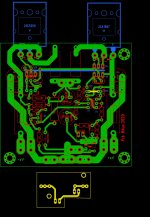
The ideal setup for the bias transistor is to mount it as close as possible to the junction of the one of the drivers the best track it's temp. If you look at Rod's PCB, you can see that he positions Q9 and Q5 right in line with each other to allow them to be coupled (with a zip tie if you look at his build pics).
As I stated, it will likely work at you have designed it. This is due largely to Q5 and Q6 running fairly cool. If you drive harder loads, this would likely change.
With all this said, it will work the way you have it, but it would likely work better if it the thermal coupling was tighter.
That looks better to me.
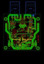
One consideration for actual assembly. Q4 is lined up with Q5. If you plan to mount the drivers on a small flat heatsink, it may be tricky to install the bolt for Q5 with Q4 blocking access to the hole.
One consideration for actual assembly. Q4 is lined up with Q5. If you plan to mount the drivers on a small flat heatsink, it may be tricky to install the bolt for Q5 with Q4 blocking access to the hole.


I like the version from post #49 better. It easier to keep Q1 & Q2 thermally coupled in that version.
Are you asking if the current mirror transistors should be thermally coupled (like Q1 & Q2)? If so, then yes it would be better if it allowed for this.
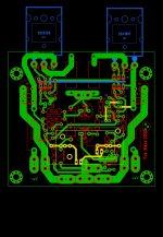
Looks good. Except that Q6 is physically blocking Q8 if you intend to mechanically fasten Q8 to a flat heatsink. Also, if you are using a flat heatsink, Q10 is backwards. Typically, you'd flip Q10 to affix it to the heatsink and then mount Q7 to its back for thermal coupling.
For Q6, you could flip it and mount it to the same heatsink at Q8. Not sure if the heat from Q6 would throw off the thermal compensation that Q7 is sensing in Q10.
For Q6, you could flip it and mount it to the same heatsink at Q8. Not sure if the heat from Q6 would throw off the thermal compensation that Q7 is sensing in Q10.
Do you have a capacitor in mind for C1? For more flexibility you could allow 2 paralleled 5mm caps to be installed on your second board, or one 5mm cap on the amp board.
- Home
- Amplifiers
- Solid State
- P3A PCB Layout