Thanks currentflow....you mean the "curve of frequency response" of an amplifier,
For a more accurate measurment you must monitor the input signal too.
Essentially, yes. But this test is only for the low-frequency response. You could monitor the input signal too, but this is only necessary if it is seen to change with reducing frequency. Your graph attachment shows a power bandwidth response which differs from a voltage response. We are interested in the -3dB frequencies here where the output voltage level drops to 0.7079 of it's nominal value.
Last edited:
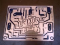
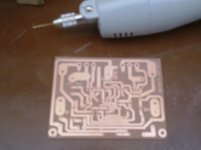
As far as I can see, there is no input cap on the pcb that Thimios used. The place is not populated (only four drill holes is visible), so it can not cause the problem with LF response.
Then maybe how about the generator output ? Some problem there ?
Scope is set at DC so that 'should' be OK.
Scope is set at DC so that 'should' be OK.
Yes ,scope is set at DC.Then maybe how about the generator output ? Some problem there ?
Scope is set at DC so that 'should' be OK.
Input capacitor is 4u7/63
This capacitor not shown in picture because i left the position empty to try some types in this position.
Thanks all for reply.
P3A
Regards.
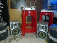
Hi friend ...as i say many times bass is strong and deep.Looking good. There's nothing wrong with that! 🙂
Regards.
P3A
Ok i try it next time.
Thanks.
Hi Sr.You have a 2channel scope.
Show both the input trace and the output trace.
Ok i try it next time.
Thanks.
i used to work for a company that represented Zeck for a while i Athens ....PT series from Zeck was very good Pro amlifiers expensive and very stable
at the time we never had a blown zeck the owner of the company had asked Zeck to provide matched sets of transitors to have for any repairs
after the company went down for other reasons i got to keep many of these sets for a very low prize
i am not willing to give away at any prize anything that is original and has a tag 1302-3281 on ( i have original toshibas also ) totally i have arround 120 pairs more and i am going to use them to construct amplifiers for my own pleasure ....in the coming years i hope to live long enough to construct 100 amps ( more )
Sir Sakis heres the pictures of my p3a project my own pcb..
Attachments
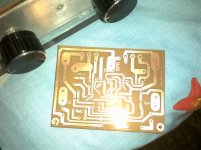
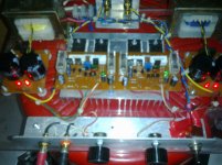
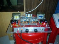
P3A
Ok sr.
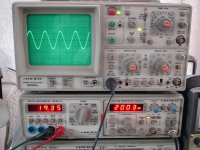
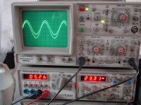
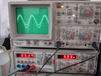
Here are in-out scopes.
first group.
Upper waveform is output.
You have a 2channel scope.
Show both the input trace and the output trace.
Ok sr.
Here are in-out scopes.
first group.
Upper waveform is output.
Attachments
-
 DSC06914.JPG612.7 KB · Views: 115
 -
 DSC06916.JPG609.5 KB · Views: 115
 -
 DSC06915.JPG614.7 KB · Views: 98
 -
 DSC06918.JPG605.2 KB · Views: 109
 -
 DSC06917.JPG609.1 KB · Views: 496
 -
 DSC06913.JPG613.1 KB · Views: 524
 -
 DSC06911.JPG614.2 KB · Views: 557
 -
 DSC06920.JPG599.1 KB · Views: 597
 -
 DSC06919.JPG605 KB · Views: 663
Last edited:


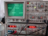
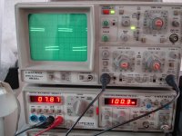
Your generator should have had flat topped square waves ! They aren't so at LF. Should have been a perfect square. Try the generator loaded only with the scope probes at 20 Hz and see if you get a perfect square. If so ,then load it with the amp and see what happens. In both cases scope should be looking at the input signal.You need to get to the bottom of this!😉
By the way, skip the sine waves. We don't need to see them now. You need to look at only one or two square wave frequencies. Maybe 20 Hz or 50 Hz and 100 Hz. You are only trying to solve the issue of the LF rolloff.
By the way, skip the sine waves. We don't need to see them now. You need to look at only one or two square wave frequencies. Maybe 20 Hz or 50 Hz and 100 Hz. You are only trying to solve the issue of the LF rolloff.
Last edited:
post412
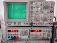
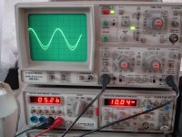
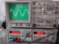
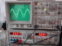
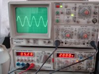
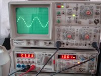
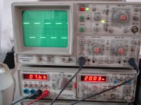
pics 2 to 4:
are the input and output on top of each other?
In pic 1 is the lower the input (nearly flat)? and the upper the output (LF roll-off)?
pics 2 to 4:
are the input and output on top of each other?
In pic 1 is the lower the input (nearly flat)? and the upper the output (LF roll-off)?
Member
Joined 2009
Paid Member
Scope probes can distort square waves - they have a resistor/capacitor divider network inside and usually they have a small adjustment screw so you can balance things out. This is why the scope has a square wave generator. It would be best to check the square wave with a simple direct piece of wire from the generator to scope input.
Yes all pictures in post #412 shown input and output on top of each other,except picture 1.post412
pics 2 to 4:
are the input and output on top of each other?
In pic 1 is the lower the input (nearly flat)? and the upper the output (LF roll-off)?
P3A
Sure but i have adjust this trimer as required.
Scoping direct on generators output(with the same probe) square wave is flat.
This time i have examine many amplifiers.
I can't see any of them with flat square wave in these low frequencies.
Then i take care to increase the value of input capacitor.
22uf is the required value to came 22Hz flat.
The problem is that never i have seen this big value capacitor in commercial amplifiers.
Scope probes can distort square waves - they have a resistor/capacitor divider network inside and usually they have a small adjustment screw so you can balance things out. This is why the scope has a square wave generator. It would be best to check the square wave with a simple direct piece of wire from the generator to scope input.
Sure but i have adjust this trimer as required.
Scoping direct on generators output(with the same probe) square wave is flat.
This time i have examine many amplifiers.
I can't see any of them with flat square wave in these low frequencies.
Then i take care to increase the value of input capacitor.
22uf is the required value to came 22Hz flat.
The problem is that never i have seen this big value capacitor in commercial amplifiers.
Last edited:
I think that this little LF anomaly is direct consequence of bootstraped VAS. It is not unexpected and is not a reason for panic. Read Elliott article about Curren sources, sinks, etc., part about bootstrap ccs. In fact, it could be the reason for good subjective impression that P3A makes.
Oops! May be I am wrong. I found Motorola application note AN485 and there is square wave response for 50Hz, 1kHz and 10kHz. 50Hz square wave has the same falling top as thimios's P3A while 1kHz and 10kHz are level. AN485 has active VAS ccs and 10uF input cap, so it seems that falling top line on the square wave amp output is caused by some other mechanism.
Fortunately there will never be any music signal resembling 50Hz square wave.
Fortunately there will never be any music signal resembling 50Hz square wave.
Last edited:
Member
Joined 2009
Paid Member
Sure but i have adjust this trimer as required.
Scoping direct on generators output(with the same probe) square wave is flat.
This time i have examine many amplifiers.
I can't see any of them with flat square wave in these low frequencies.
Then i take care to increase the value of input capacitor.
22uf is the required value to came 22Hz flat.
The problem is that never i have seen this big value capacitor in commercial amplifiers.
I can't say I've ever tested an amp with a square wave at such low frequencies so I don't know if it is a problem or not. I tend to use the square wave from my scope because it's so clean whereas my variable frequency signal generator is not that great but does let me measure gain as a function of frequency. Once I did use a square wave at 20KHz and it fried the amplifier. I read a bit about the stupidity of what I did and that there may be little value in testing at such high frequencies with square waves so I don't do that anymore. From what you are saying, it sounds like it is not a problem. Does the amplifier sound good - yes? - then there's no problem 🙂
- Home
- Amplifiers
- Solid State
- P3A Comparison table ( long .... )