In my P3A build, at about 1.4K (trimmer resistance) I got the ideal 75ma but now I had it at 1.8k that is about 25-30ma.
@Ian Finch,
I finally manage to do measurements across 0.33R as per your suggestion;
No music-
after 20secs = 47.2mv
1min = 48.3mv
5mins = 50.5mv
With music playing-
after 20secs = 50.8mv
1min = 51.0mv
5mins = 52.0mv
At power on my DMM is not capable of getting a fixed reading..too slow 🙁
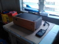
My P3A has its new home...
@Ian Finch,
I finally manage to do measurements across 0.33R as per your suggestion;
No music-
after 20secs = 47.2mv
1min = 48.3mv
5mins = 50.5mv
With music playing-
after 20secs = 50.8mv
1min = 51.0mv
5mins = 52.0mv
At power on my DMM is not capable of getting a fixed reading..too slow 🙁
My P3A has its new home...
Attachments
Is your highest reading of 52mV across one 0r33, or across two series connected 0r33?
This would be equivalent to 26mVre across each emitter resistor.
The lowest 50.5mV after 5minutes of warm up is ~25.2mVre.
This may be enough to minimise (avoidable) crossover distortion.
Maybe you should set this very slightly higher? 26mVre or 27mVre?
BUT !!!!!!
PA3 is not an emitter follower (EF) output stage.
It is a CFP style.
According to D.Self the Vre should be set MUCH lower to minimise crossover distortion.
What does ESP have to say for minimising crossover distortion?
Last edited:
^across each of 0.33R (at - & + rail). I wanted to have it lower because the
new case cannot handle the heat genarated at 75ma bias current. I think ESP
states that at <20ma distortion becomes audible.
new case cannot handle the heat genarated at 75ma bias current. I think ESP
states that at <20ma distortion becomes audible.
Circuit designer of P3A Rod Elliott says:
Setting Quiescent Current
Testing has shown that the quiescent current can be as low as 20mA without evidence of visible or audible crossover distortion (13mV across the two 0.33 ohm resistors).
End of quote.
My P3A has quiescent current 15mA (10mV across two 0.33 ohm resistors).
Setting Quiescent Current
Testing has shown that the quiescent current can be as low as 20mA without evidence of visible or audible crossover distortion (13mV across the two 0.33 ohm resistors).
End of quote.
My P3A has quiescent current 15mA (10mV across two 0.33 ohm resistors).
Last edited:
Nice project 🙂.....I finally manage to do measurements across 0.33R as per your suggestion;
No music-
after 20secs = 47.2mv
1min = 48.3mv
5mins = 50.5mv
With music playing-
after 20secs = 50.8mv
1min = 51.0mv
5mins = 52.0mv......
It would seem to be in control at your playing level, at least. I couldn't find our posts that refer to this though.
20 mA is fine for CFP designs like P3A and technically, even 12mA or so will be fine but I think Rod Elliott and most people I know that built it, will be using it with the suggested 75mA bias, as has been recommended for many years. However, I don't recall where your quotation came from Ivan, but this is all Rod says about bias in the P3A article on his site that I just rechecked:
I think you can take it that the recommendation above is correct and for personal stereo use, I certainly agree. Ask Sakis too 😉 but it seems no one has been paying attention to earlier posts or reading the instructions on the ESP site.Connect a multimeter between the collectors of Q7 and Q8 - you are measuring the voltage drop across the two 0.33 ohm resistors. The most desirable quiescent current is 75mA, so the voltage you measure across the resistors should be set to 50mV ±5mV. The setting is not overly critical, but at lower currents, there is less dissipation in the output transistors. Current is approximately 1.5mA / mV, so 50mV will represent 75mA quiescent current.
In a reversal of this, if I were to use this as a utility amplifier or part of some active crossover speakers as Rod does, I suspect that lower, even optimum bias (around 15 mA) will instead prove to be the better performance choice (and much cooler). The reasons for this are not difficult to work out and if you are going to build a multi-way active speaker set, you'll have plenty of time to find out.
Using modern, high linearity output transistors does improve the sound at low bias levels on both EF and CFP but not as much as simply setting a higher bias, which makes it a better sounding amplifier for personal stereo listening, regardless of parts quality.
I'm speaking not from point of view of lowest THD, but what sounds most enjoyable to listen to over extended periods with various types of music. Entertainment is about enjoyment rather than building monuments to technical excellence and this has always shown in the poor sales of many otherwise excellent products. Just go to the start of thread again and read a little of what Sakis has been saying 😉
Edit to above: Sorry Ivan, I should have said that you were quoting Rod's minimum bias guidelines for use where smaller heatsinks and lower temperatures were desirable. That's not the same as the recommended bias for best performance.
Quote is from ESP Assembly Instructions for P3A, that one gets only when buying the original ESP boards. Assembly Instructions has additional useful info that is not available in articles on Rod's site.
Quote is from ESP Assembly Instructions for P3A, that one gets only when buying the original ESP boards. Assembly Instructions has additional useful info that is not available in articles on Rod's site.
interesting......😎
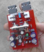
i built that output stage before and what i did was to use 0.1 ohm where the resistors were 0.33 and then 0.22 ohms of the emitter of the power trannie...
sound was very good as i recall....
Another quote from assembly instructions:
The desired quiescent current is between 25 and 100mA, so the voltage you measure across the resistors should be set to between 16.5mV and 66mV.
End of quote.
I think that Rod suggests 75 mA in the article as a safe level for most diy-ers. He doesn't know what kind of output transistors will be used by any of the builders that will use the schematic from the article, so he probably thinks that it's better in most cases, to err on the high side of optimum bias.
Increasing the output bias increases the ClassA level considerably.
Using this set up method one listens to low level audio in ClassA and that sounds better.
eg 75mA output bias gives 150mApk of ClassA current and that is -27dB ref 50W
Listen at average levels below that and you stay in ClassA for most of the programme.
15mA gives a max ClassA ref 50W of -41dB. Much of the average signal level will be above ClassA and using the feedback to reduce the crossover distortion. This design is not an ultra low distortion amplifier.
Operating substantially in ClassA will probably sound good, when the low average listening levels suit.
A Roender with 555mA of bias has the ClassA limit @ ~ -10dB ref 50W, i.e. it will replay @ 17dB louder than a high bias P3A and still stay in ClassA.
Last edited:
here we do electronics ...words like maybe, probably or perhaps should be out of the picture ...slew rate anyone ?
I used the word "probably" in the third paragraph.
Does that mean East considers my comment to not be about electronics?
Does that mean East considers my comment to not be about electronics?
Andrew we know each other way too long to understand each other's humor ( i expect ...)Slew rate anyone ?
Nice project 🙂
It would seem to be in control at your playing level, at least. I couldn't find our posts that refer to this though.
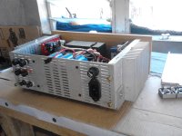
It refers to this arrangement (attached photo), by the way I have biased my P3A at 100ma for a test, I could not hear any sonic differences between the minimum 20ma however at 2 hours playtime heatsink was totally HOT to the touch. I have settled to 22ma (15mv across two 0.33r) and I am satisfied with it. Heatsink is barely warm after 4 hours of playtime at minimum vol level.
I have replaced the MJE drivers with Fairchilds 2SC4793/SA1837, Sakis was right the MJEs sounds metallic, the only noticeable thing was that the highs is crispy clean but seems to be lacking in bass punch.
Attachments
Sakis,
I couldn't say I like one in particular, I listened to different type of genre but
I like melodies so I figure rock and jazz fits in 🙂
When I test my amp built I play "Principles of Desire" by the Jazz group Rippingtons and the classic "I Won't Hold You Back" by Toto and for a heavier one "For the Love of God" by Steve Vai. 😉
What slew rate, Sakis? I think 100 KHz bandwidth limit for 35V rails is plenty and that's around 40V/us.
Here's trivial calculator for anyone in doubt : Slew Rate Calculator
Here's trivial calculator for anyone in doubt :
Slew Rate CalculatorIan it will take a few days to answer that since i am not ready yet ..in between i am fishing ....
- Home
- Amplifiers
- Solid State
- P3A Comparison table ( long .... )