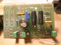
Is this a copy from original Elliot's pcb?Hey guy's
I'm currently fitting the transistors and have Q5 and Q6 on a common heat sink.
Does Q4 need to be on a heat sink too?
Kind regards
Roy.
The ESP logo and general appearance says they are ESP PCBs.Is this a copy from original Elliot's pcb?
The ESP logo and general appearance says they are ESP PCBs.
I don't think so ,except if someone has cut the top of pcb.
Attachments
The ESP logo and general appearance says they are ESP PCBs.
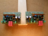
I agree, cut in half and trimmed.
All Genuine here!
Hi Folks,
Yes, they are original PCB's purchased from the Rodd Elliot web site. I have split them because at a later point in time I'm hoping to go dual mono by adding a second transformer, rectifiers and capacitance.
And yes, I have also trimmed the top of the PCB's as I want to mount them close to the heatsinks with the outputs standing up.
Hope I havent done anything wrong! 😱
Kind Regards
Roy.
P.S.
Hi Mr Sakis, - No, I dont party every night - but I do like realistic listening levels 😀
Hi Mr Thimios, - The cap you highlighted on my PCB is a PSU decoupling cap which is shared between the two boards. So with splitting them I will be placing a +ve and -ve decoupling cap to each PCB where the fuses go. The fuses will be off board.
Last edited:
Hi Folks,
Yes, they are original PCB's purchased from the Rodd Elliot web site. I have split them because at a later point in time I'm hoping to go dual mono by adding a second transformer, rectifiers and capacitance.
And yes, I have also trimmed the top of the PCB's as I want to mount them close to the heatsinks with the outputs standing up.
Hope I havent done anything wrong! 😱
Kind Regards
Roy.
P.S.
Hi Mr Sakis, - No, I dont party every night - but I do like realistic listening levels 😀
Hi Mr Thimios, - The cap you highlighted on my PCB is a PSU decoupling cap which is shared between the two boards. So with splitting them I will be placing a +ve and -ve decoupling cap to each PCB where the fuses go. The fuses will be off board.
Yes i believe that the right way isn't cutting the board because this piece of board is useful for heat sensing from out transistors to Vbe multiplier
Absolutely. This isn't an EF (emitter follower) output stage amplifier - it's a CFP design and the most appropriate temperature range for bias control is sensed at the driver stage. Note how close Q9 and Q6 are located. That is all the coupling you need with Rod's ESP board, just like it was designed. 🙂The heat sensor om a P3A is to the driver transistors. NOT to the PCB !
As this is Rod's IP and he has requested we don't show product details, visit the site and see details: 60-80W Power Amplifier
Phew!
So I havent bol***ed it all up then! - thats good to know.🙂
Agreed absolutly.
Kind Regards
Roy.
So I havent bol***ed it all up then! - thats good to know.🙂
As this is Rod's IP and he has requested we don't show product details, visit the site and see details...
Agreed absolutly.
Kind Regards
Roy.

nikosokey, do you have the permission of Rod Elliot to use the P3A trademark and to associate your PCB's with that product ?
If you can show that you have then all the deleted posts can be reinstated.
Υou're right.t I did not notice. Ι interested to show more results from this amp .You can bring all my Post except the photo with logo P3A.
i hope the moderator Molly bring on the forum my results for this amp clone or if he cant do it ,give me permission to post again my result without any photo against the rules.
Nikos.
Nikos.
Nikos, you can post results of your P3A build and as many pictures of your own build as you want but you can't then go on to produce and offer those boards for sale.
Once you associate your boards specifically to the P3A (which by inference is what posting in this thread does) then that is infringement of Rods work.
Once you associate your boards specifically to the P3A (which by inference is what posting in this thread does) then that is infringement of Rods work.
Nikos,
I would like to see results concerning your build of P3A in this thread.
I second that

Actually me too, I have the PCBs from Rod, but never assembled them, let's see if it is worth the effort.
I second that
Don't worry my friends i post again my results soon when i have free time.
Hi All,
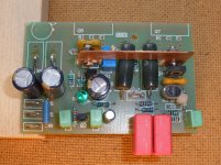
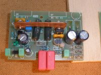
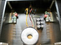
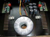
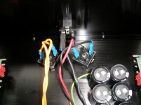
Here's some more pictures showing my progress. Not the prettiest of builds I'm sure but hopefully okay. Boards are complete now apart from the outputs and I am ready to build it all into the case. Trouble is, I'm not really sure about how to lay it all out. I was thinking about making it dual mono once I knew it worked okay. But now I'm wondering if having two transformers would really make that much difference. Could I have just have one tx feeding two sets of rectifiers and capacitor banks (one for each board)?
Any way I'd be grateful if you could have a look over my boards and let me know if there's anything amiss.
Also, does it seem okay the way its laid out, or is there a better way?
Thanks all
Kind Regards
Roy
Attachments
- Home
- Amplifiers
- Solid State
- P3A Comparison table ( long .... )