I did a sim, without the beads, for which I have no details.
As you can see, for a 10mV peak@1Khz, distortion is ridiculously low, far below 1ppm.
Gain@1Khz is 32dB.
LF noise up to 500Hz is as expected between 5.5 and 7nV/rtHz
Hans
As you can see, for a 10mV peak@1Khz, distortion is ridiculously low, far below 1ppm.
Gain@1Khz is 32dB.
LF noise up to 500Hz is as expected between 5.5 and 7nV/rtHz
Hans
Attachments
Last edited:
Hi Hans,
Just tried it, remains very noisy with 1R to GND (first sim was incorrect).
Somehow if I transformer couple the input I see much reduced noise. About 250nV/SQRT Hz without and 25nv/SQRT Hz with Xformer.
Can't really explain that, maybe you have an idea?
Indeed I increased the AD8429 gain to ~50X
Just tried it, remains very noisy with 1R to GND (first sim was incorrect).
Somehow if I transformer couple the input I see much reduced noise. About 250nV/SQRT Hz without and 25nv/SQRT Hz with Xformer.
Can't really explain that, maybe you have an idea?
Indeed I increased the AD8429 gain to ~50X
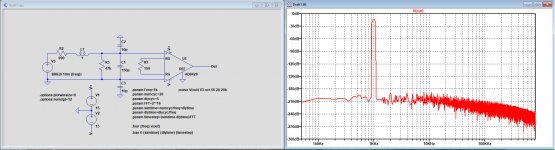
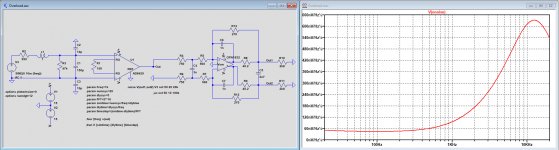
I did a sim, without the beads, for which I have no details.
As you can see, for a 10mV peak@1Khz, distortion is ridiculously low, far below 1ppm.
Gain@1Khz is 32dB.
LF noise up to 500Hz is as expected between 5.5 and 7nV/rtHz
Hans
Hi Hans,
That's very different from what I see in my SIM, must be due to TINATI I guess.
Attachments
Last edited:
Well, in my sim I see much more noise when I directly couple the cart to the input of the AD8429 vs when I transformer couple it. By as much as a factor of 10.
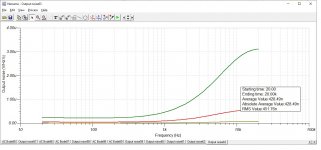
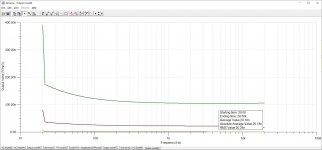
TinaTI doesn't have a FFT output as you showed, but it can show the output noise.
Edit: output noise with xfrm attached, circuit is otherwise the same as for the graph above.
TinaTI doesn't have a FFT output as you showed, but it can show the output noise.
Edit: output noise with xfrm attached, circuit is otherwise the same as for the graph above.
Attachments
Last edited:
I still don't understand your graphs, what do they show, under what conditions and taken at which point ?
Anyhow, here are the noise spectra taken resp. at the output of the AD8429 called V(onoise) and referred to the input at the Cart's voltage source V3 called V(inoise).
Hans
Anyhow, here are the noise spectra taken resp. at the output of the AD8429 called V(onoise) and referred to the input at the Cart's voltage source V3 called V(inoise).
Hans
Attachments
Ah my apologies, can be difficult to get my point across in a post.
Input signal is Voltage generator 1, 7.78mVp @ 1KHz sine wave.
Output is measured at VM3 (output of the LPF after OPA1632).
So basically the whole analog front end of the "digital" riaa preamp.
Does that make sense?
Input signal is Voltage generator 1, 7.78mVp @ 1KHz sine wave.
Output is measured at VM3 (output of the LPF after OPA1632).
So basically the whole analog front end of the "digital" riaa preamp.
Does that make sense?
Attachments

I have added the OPA1632.
First image shows the FR with shorted Cart.
I have reduced the 10nF in front of the OPA1632 to 3nF to get a FR that is at least within 0.2dB u to 20Khz, which should be the absolute minimum.
10nF is simply too much.
Second image shows the overall noise at the output over the 2n7 cap just as your VM3, now with the Cart in place.
Hans
Attachments

Hi Hans,
It's part of the PCM4222EVM (the A/D board from TI I'm using). It's buffering the PCM4222 ADC CM output voltage to drive the OPA1632 Vocm input.
It's part of the PCM4222EVM (the A/D board from TI I'm using). It's buffering the PCM4222 ADC CM output voltage to drive the OPA1632 Vocm input.
Well, in my sim I see much more noise when I directly couple the cart to the input of the AD8429 vs when I transformer couple it. By as much as a factor of 10.
TinaTI doesn't have a FFT output as you showed, but it can show the output noise.
Edit: output noise with xfrm attached, circuit is otherwise the same as for the graph above.
What is the turns ratio of the transformer and is the magnetizing inductance large enough not to make the transfer collapse when you have the cartridge impedance in place?
Hi Hans,
It's part of the PCM4222EVM (the A/D board from TI I'm using). It's buffering the PCM4222 ADC CM output voltage to drive the OPA1632 Vocm input.
I looked at the PCM4222EVM and noticed that U3 has 1K at its input with a 0.1uF cap. This makes much more sense as the almost 10K without a cap that you are using.
The other thing is that you placed a filter with the 10nF in front of the PCM4222, thereby seriously restricting BW.
What sample rate have you in mind to restrict BW that much ?
Hans
The PCM4222 controls sample rate in the decimation stage. Whatever you output the SD ADC runs at the same speed. So to me out of band up to a few 100kHz is automagically removed?
What is the turns ratio of the transformer and is the magnetizing inductance large enough not to make the transfer collapse when you have the cartridge impedance in place?
Hi Marcel,
It's a model of the Jensen JT-11P-1HPC, 1:1 turns ratio. RMS voltage @ VM1 is 5.35mV (7.566mVp) @ 1KHz with VG1 @ 7.78mVp@ 1KHz. So I don't think it's loading down the cart to much.
I looked at the PCM4222EVM and noticed that U3 has 1K at its input with a 0.1uF cap. This makes much more sense as the almost 10K without a cap that you are using.
The other thing is that you placed a filter with the 10nF in front of the PCM4222, thereby seriously restricting BW.
What sample rate have you in mind to restrict BW that much ?
Hans
It was my (bad) attempt at simulating the output impedance of the Vcom pin of the PCM4222. I've updated the sim (increased impedance of voltage source and corrected the LPF).
I'm currently running the A/D @ 48KHz 24 bit, feeding a miniDSP that's doing the RIAA and subsonic filtering, with some room to spare to EQ the cart if I ever come to that point.
I've updated the 10nF to 2.7nF to increase the BW at that point.
Attachments

Last edited:
The PCM4222 controls sample rate in the decimation stage. Whatever you output the SD ADC runs at the same speed. So to me out of band up to a few 100kHz is automagically removed?
Well output BW is limited by the Nyquist sample rate limit, but still why feed the ADC will all sorts of out of band hash and noise? Can't really do anything positive, right?
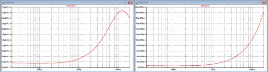
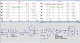
I have made some of the properties without and with transformer visible in the images below.
First image shows the FR and the second one the Noise spectra.
I have modelled the complete Jensen transformer including series resistances and parallel capacitances.
It must be obvious that inserting this transformer gives no improvement.
I could have lowered the 47K resistor to remove the bump at 6kHz, but this would have even worsened the situation at 20Khz, now already -14dB.
But the FR without transformer is also nothing to write home about, with -10dB at 20Khz.
So you will have to invest some more time and maybe you should shift to LTSpice instead of using TINA.
Hans
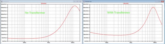
Attachments
Isn't that 10 dB roll-off just the normal roll-off of the cartridge inductance and load?
Looking at just the inductive and resistive parts to keep the calculation simple:
1/(2 pi (1 H/(47 kohm + 990 ohm))) ~= 7637.845719 Hz
10 dB*log10(1/(1 + (20 kHz/7480.282325 Hz)^2)) ~= -8.952428583 dB
Presumably the mechanical transfer has a substantial peak just below 20 kHz.
Looking at just the inductive and resistive parts to keep the calculation simple:
1/(2 pi (1 H/(47 kohm + 990 ohm))) ~= 7637.845719 Hz
10 dB*log10(1/(1 + (20 kHz/7480.282325 Hz)^2)) ~= -8.952428583 dB
Presumably the mechanical transfer has a substantial peak just below 20 kHz.
I'm currently running the A/D @ 48KHz 24 bit,.
You aren't. The ADC runs at a fixed rate and it's digitally filtered with some pretty steep filters to produce the required PCM output.
Well output BW is limited by the Nyquist sample rate limit, but still why feed the ADC will all sorts of out of band hash and noise? Can't really do anything positive, right?
It's a personal decision, but worth checking the filtering you get for free. Single pole LPF is possibly all you need in the analog domain.
- Home
- Source & Line
- Analog Line Level
- Overload margin in Phono pre-amp