The cart is in a metal screening box which is connected to one pin. In theory this needs it's own wire
Right so probably L- or R- is connected to the case inside the cart. Not ideal but also not much I can do about.
Should be easy enough to check with a dmm with one lead on the cart body and the other on the output pins. I guess that wouldn't harm the coils.
Most AT's have a tab that can be removed with delicacy. Yours sadly doesn't
To bad, anyway, another reason to upgrade some time in the future.
Going back to the PCM4222EVM. Do you know if there is a DC offset on the XLR input pins? I think I read somewhere there is but can't find it anymore. If so it would be the Vcom from the PCM4222 on the OP1632 input pins, right?
Placed my order @ Mouser.
Should be in in a couple of days. Will report back once I got it all hooked up!
In the mean time, any good sources for BiQuad calculators / info? I don't like the one supplied by miniDSP. It has to much gain build in (+35dB @ 20Hz)
Should be in in a couple of days. Will report back once I got it all hooked up!
In the mean time, any good sources for BiQuad calculators / info? I don't like the one supplied by miniDSP. It has to much gain build in (+35dB @ 20Hz)
Last edited:
On the PCM4222 from Wayne Kirkwood
When the inputs are not connected and left floating there is a 1.95 VDC common mode (i.e. relative to ground) potential on the input connector's tip and ring.
If DC-coupled to the source, the source will have to sink about 3.5 mA from each input.
This will force op amp outputs driving the PCM4222EVM into class-A so its not as bad as it may seem.
Just be aware that there is current-limited DC on the inputs.
The differential voltage between inputs however is essentially 0V.
A differentially-connected transformer wired to pins 2 and 3 on this input does not see significant secondary DC current flow.
If the transformer has a center-tap it should be left floating.
On the PCM4222 from Wayne Kirkwood
Thanks! I know I seen that somewhere. I've ordered a couple of coupling caps also, guess I'll be using them
That's a lot of info, thanks!
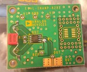
A couple of things are a given for now. The cart is almost new so I would like to keep that. Termination resistors are also a must so that's another one that's fixed. The instrumentation amp is of course a variable to play with. I am planning to order some EVAL-INAMP-82RZ boards. Those come with an assortment of amps included.
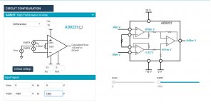
The AD8221 is one of them, could be a better option, 40fA/sqrt(Hz) and 8nV/sqrt/(Hz).
Another one is the AD8421, 200fA/sqrt(Hz) and 3nV/sqrt(Hz).
Since they are included I think I will start with the AD8221, slew rate is only 2.5V/uS, but that should still be more than enough considering max 22Khz and 0.56Vpk typical output.
Voltage noise from the amp itself will probably be around 10nV/sqrt(Hz) with a gain setting of 17.3dB. Current noise from the amp should be about 30x lower compared to the AD8429. I'll add some 6K8 resistors to my basket to set the gain.
The AD8221 and AD8421 would indeed be better with respect to noise.
Regarding the termination resistor: you can make a circuit with a resistive input impedance and less than thermal noise if you really want to. The first such circuit that I know of was made around 1939 by W. S. Percival and W. L. Horwood (W. S. Percival, "An electrically "cold" resistance", The wireless engineer, vol. 16, May 1939, pages 237...240). Since then such techniques have become quite popular for RF low-noise amplifiers, although only few people use them for terminating moving-magnet cartridges.
Attachments
If I can remember which thread I will link to the sims done on cooled loading based on some things Self and Cordell did. Short answer ISTR was there was no point for 47k but comes in handy if you want to create the 75us pole by loading down the cartridge.
I did some calculations and measurements long ago to see how much you can win by replacing the 47 kohm resistor with a lower noise version. For a Shure V15-III the difference was about 3 dB(A) best case, for a Marantz 500 cartridge about 2.27 dB(A) best case.
Best case means that this is the improvement when you replace the 47 kohm resistor with a completely noiseless one while all other noise contributions in the phono amplifier are zero and there is no record playing. Like Bill already wrote, the difference gets larger when you use a lower termination resistance than the standard 47 kohm.
Best case means that this is the improvement when you replace the 47 kohm resistor with a completely noiseless one while all other noise contributions in the phono amplifier are zero and there is no record playing. Like Bill already wrote, the difference gets larger when you use a lower termination resistance than the standard 47 kohm.
I did some calculations and measurements long ago to see how much you can win by replacing the 47 kohm resistor with a lower noise version. For a Shure V15-III the difference was about 3 dB(A) best case, for a Marantz 500 cartridge about 2.27 dB(A) best case.
Best case means that this is the improvement when you replace the 47 kohm resistor with a completely noiseless one while all other noise contributions in the phono amplifier are zero and there is no record playing. Like Bill already wrote, the difference gets larger when you use a lower termination resistance than the standard 47 kohm.
Interesting stuff, does seem to indicate that optimizing the rest of gain structure is potentially more useful. Could be the icing on the cake.
For now, first getting everything hooked up and configured. Will do the SMD soldering tomorrow at work in my lunch break.
Also found a Bi-quad setting which seems to work and has an indicated +/-0.14dB accuracy:
; inverted filter for phono playback (48kHz):
;
; b = [ 0.2275882473429072 -0.1680644758323426 -0.0408560856583673 ]
; a = [ 1.0000000000000000 -1.7160778983199925 0.7179700042784745 ]
MiniDSP equivalent (edited by me)
B0= 0.2275882473429072
B1= -0.1680644758323426
B2= -0.0408560856583673
A1= 1.7160778983199925
A2= -0.7179700042784745
Last edited:
48k has less accuracy. At 96k 2 biquads gives +-0.000010dB accuracy! In reality the lathes were likely +/- .2dB
48k has less accuracy. At 96k 2 biquads gives +-0.000010dB accuracy! In reality the lathes were likely +/- .2dB
Not really want to run @ 96KHz just for RIAA accuracy. Seems a bit silly.
I'll purchase Scott Wurcer's Linear Audio publication "Record replay RIAA correction in the digital domain".
Looks like that contains exactly what I need.
I run my miniDSP at 96kHz anyway and the PCM4222 is actually a SD ADC so runs at a fixed rate and just decimates to suit whatever you ask of it. Then becomes a coin toss of whether you want the extra PEQs you get at 48kHz
I run my miniDSP at 96kHz anyway and the PCM4222 is actually a SD ADC so runs at a fixed rate and just decimates to suit whatever you ask of it. Then becomes a coin toss of whether you want the extra PEQs you get at 48kHz
I'm currently running the openDRC 2x2 plugin, that's limited to 48KHz I think. Running at 96KHz will also limit the number of FIR taps available. I don't need the extended frequency response, so if possible 48KHz is my preference.
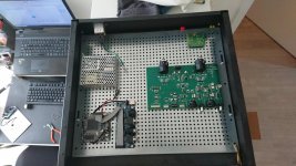
Analog pre-amp boards soldered! 23K7 0.1% to ground from both legs on the input, 47pF differential. 6K8 0.1% gain set resistor.
The power supply bypassing caps are on the other side.
Attachments
Last edited:
Hi all,
Been busy slowly getting everything build. Cables, CLC filter board for the analog supplies, InAmp boards, ...
Also been busy recalculating the optimal gain for the analog front end, given the following parameters:
Max input level from cart: 0.156mVpp (5.5mV rms @ 1KHz +20dB @ 20KHz)
Desired input level to ADC bord: 1.187928Vpp (-20dBFS)
Desired gain in analog front end: ~7.6X
So I ended up with the attached config. Does that seem right?
Attachments

Last edited:
Edit last post, can't delete attachment
Made a couple of errors I just realized.
Attached modified configuration (back to what is was, must stop going over these things over and over...)
Made a couple of errors I just realized.
Attached modified configuration (back to what is was, must stop going over these things over and over...)
Attachments
Last edited:
Why do you map the expected maximum level from the cartridge to -20 dB? To keep headroom for scratches or inaccuracies in your estimate?
What noise level do you get when you divide the ADC's input noise by the preamp gain?
I can't read the pictures, for some reason I only get a very poor resolution version on my screen.
What noise level do you get when you divide the ADC's input noise by the preamp gain?
I can't read the pictures, for some reason I only get a very poor resolution version on my screen.
- Home
- Source & Line
- Analog Line Level
- Overload margin in Phono pre-amp