It's nice that you have no 50 Hz transformer nearby, but switched-mode power supplies often draw nasty, grossly distorted current spikes from the mains, so I would check the impact of the distance between the amplifier and the power supply anyway, or do what Hans suggested and temporarily run everything off batteries.
Last edited:
Can you post the exact circuit that you are using at this moment.
Results compared to LTSpice simulations are usually very close.
And at what point did you measure THD and noise.
Maybe you can show the noise spectrum behind the AD8421, that could reveal something.
And you could temporarily try two 12V batteries to exclude eventual ground loops.
Hans
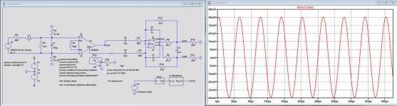
Current setup schematic attached. Swept sine measurement is running, takes a while, I'll post it when ready.
Attachments
Mark,
I read the specs of your ADC and noticed that input should be exactly differential, so you need the inverter after the AD5121 after all.
Each ADC input can max. handle 2.8Vpp.
To get 2.8Vpp with the current setup when using a 70mVrms Cart signal, you should use a 250R resistor for the AD5121 and you have to lower the input resistances for the ADC from 750R to 390R.
Hans
Attachments
Hi Hans,
I'm aiming at -20dBFS input to the ADC, both as headroom for pop & clicks and to keep it in the most linear operating area.
So I figure I need 395mV rms @ 20KHz to reach that, that translates into 39.5mV @ 1KHz w/ RIAA.
Now that sets my required gain at 20*LOG(39.5/5.5)=17.12dB
Measurement with the current (AD8221) setup attached.
Attachments

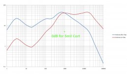
In the image below, you see the max level according to Holman coming from an LP playing music
You also see the 0dB@1Khz point.
Ridiculous high levels at 20Khz are non existing and the highest level you will see is ca 50mV pre Riaa.
Put some margin on top of this for pops and cracks and settle on 100mVrms
The 395mVrms that you quote is really over the top.
The calculation you make is not for gain, but for headroom.
What you need is 5.6Vpp differential on the ADC, or 2Vrms at max level.
To get this, gain should be 2V/100mV=20 or the equivalent of 26dB.
Hans
Attachments
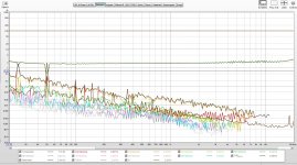
Mark, the distortions you are showing are insane.
My question is again, at what point are you measuring and is it with the circuit diagram in #122 ?
When I know how and where you measure, I will do the simulation for you with exactly the same circuit.
Hans
My question is again, at what point are you measuring and is it with the circuit diagram in #122 ?
When I know how and where you measure, I will do the simulation for you with exactly the same circuit.
Hans
Hans,
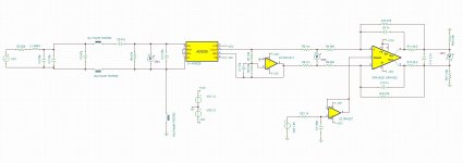
This is measured at the DSP output, signal chain is:
Focusrite 8i6 analog output - anti RIAA filter - AD8221 gain stage - PCM4222EVM - miniDSP - Focusrite 8i6 SP-DIF in.
Something is really not OK, that's for sure..
This is measured at the DSP output, signal chain is:
Focusrite 8i6 analog output - anti RIAA filter - AD8221 gain stage - PCM4222EVM - miniDSP - Focusrite 8i6 SP-DIF in.
Something is really not OK, that's for sure..
I don't understand the Anti Riaa filter, but what I get is that you feed the Anti Riaa filter with a 20Khz 395mVrms signal, resulting in 39.5 mVoltrms at the input of your pre amp, right ? That's 55.3mVpeak.
What is the distortion of this Anti Riaa filter at 395mVrms input ?
And as in your circuit diagram in #122 the Cart is still part of the circuit or not ??
With the 6K8 at the AD8221 that you show, voltage on the ADC will then be 80mVpp instead of the 5.8Vpp.
So your signal is almost 40dB too low.
I will be glad to help you, but please come with complete details and first get the gain to a sufficient level.
Hans
What if you connect your Focusrite directly to the PCM4222EVM module ?
What distortion do you get in that case ?
Hans
What distortion do you get in that case ?
Hans
Hi Hans,
Running that measurement right now. I don't know the exact level of the input signal. Calibrated it to -12dbFS with REW (output of the adc)
But before we get really into much detail, I've ordered parts @ Mouser yesterday to upgrade the setup to the AD8421 with level shifter. Once I completed that I'll report back.
Hans, I think Wayne Kirkwood did some measurements on the TI EVM. I'll try and find if there is a disortion measurement at that level.
Hi all,
Small update to let you know I'm still working on this project, not progressing as fast as I would like 🙁 Been really busy at work.
I decided to wire up the XLR inputs, connected in parallel to the RCA inputs and build new interconnects.
Used Belden 9272 twinax cable I had a couple of meters of from an old project. Shield only connected at the XLR side (preamp input). Used Neutrik NC3MXX-B and nf2c-b/2 connectors. Cable capacitance is about 70pF.
Placed a capacitance multiplierboard (Capacitance Multiplier) I also had collecting dust on the digital 5V power supply (cranked up the power supply to 5.8VDC before the multiplier).
That pretty much solved the 50Hz interference problem.
Also ordered a LT3045/LT3094 (LT3045/LT3094 Ultra Low Noise Dual Polarity Power Supply) regulator board from LDOVR.com to clean up the analog power supply (+/-12V out).
So next up is further modifying the power supply when the LT3045/LT3094 board arrives and modifying the inamp boards.
When that's all done a new round of measurements!
Hi all,
Another update.
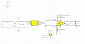
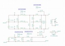
I've build the attached schematic. Inamp for now is a AD8228 (AD8421 was not in my collection 😡).
Performance is getting better, still trying to silence the power supply, starting to regret the Meanwell SMPS... Added a CM choke on the +/-15VDC supply and one on on the +5VDC. That helped but still seeing a subharmonic switching artefact. Wandering between 300 and 330Hz.
Noise floor out of the ADC is now about -110dBFS, but the ~315Hz switching artefact is messing things up, it's audible. DSP isn't going to save the day because it's not on a fixed frequency.
I did implement a very high Q 50 and 100Hz notch filter (Q=50, G=-16dB) to remove these interferers picked up by the cart.
Also have a new cart coming, an AT 440MLb body with a VML40ML stylus, and an extra Pioneer pc-hs01 headshell.
Another update.
I've build the attached schematic. Inamp for now is a AD8228 (AD8421 was not in my collection 😡).
Performance is getting better, still trying to silence the power supply, starting to regret the Meanwell SMPS... Added a CM choke on the +/-15VDC supply and one on on the +5VDC. That helped but still seeing a subharmonic switching artefact. Wandering between 300 and 330Hz.
Noise floor out of the ADC is now about -110dBFS, but the ~315Hz switching artefact is messing things up, it's audible. DSP isn't going to save the day because it's not on a fixed frequency.
I did implement a very high Q 50 and 100Hz notch filter (Q=50, G=-16dB) to remove these interferers picked up by the cart.
Also have a new cart coming, an AT 440MLb body with a VML40ML stylus, and an extra Pioneer pc-hs01 headshell.
Attachments
Hi all,
Another update,
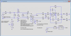
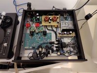
I've been busy getting the power supply cleaned-up. I've build the atteched filter. All is good now, looks pretty clean.
Also replaced the AD8228 with the AD8421 and build the attached "cold resistor". Still need to mount those. When all is up and running I'll post some measurements.
The OPA1656 seems to offer the best performance in the cold resistor circuit of all op-amp's I simmed (quite a lot of them), still not really sure what parameter is most critical for the noise performance in this application. Any toughts?
Another update,
I've been busy getting the power supply cleaned-up. I've build the atteched filter. All is good now, looks pretty clean.
Also replaced the AD8228 with the AD8421 and build the attached "cold resistor". Still need to mount those. When all is up and running I'll post some measurements.
The OPA1656 seems to offer the best performance in the cold resistor circuit of all op-amp's I simmed (quite a lot of them), still not really sure what parameter is most critical for the noise performance in this application. Any toughts?
Attachments

1) Do you mean what input noise parameter for the best S/N ?
As long as your S/N with Cart connected is above 75dBA, it doesn't matter how much (white) current or voltage noise is contributing.
With a lower voltage noise you can allow some more current noise and vice versa.
And concerning your cold resistor, where and how does it connect and why do you need it in the first place with a S/N that is probably already sky high.
2) What I don't understand at all is the 300Hz power supply hum problem that you are facing.
That sounds like bad earth connections or gnd loops.
How and where are your analog gnd and your mains gnd connected to each other ? Could you give a schematic layout ?
Does your Meanwell feed the amp directly or is there a proper voltage regulator in between ?
I use Meanwell SMPS wall warts without the slightest effect in the audio band, only the ca. 50Khz switching frequency has to be taken care of,
Hans
Hi Hans,
The 300 ish Hz was coming from the Meanwell PSU. I've eliminated it by using 100nF capacitors from the DC lines (+5, +15, -15, GND) to PE. Since it was wandering between 300 and 330Hz I guess it was a subharmonic of some sort of the switching?
I use a board with LT3045 and LT3094 regulators to provide clean +/-12VDC (regulators after the DM filter).
Mains ground (PE) and signal ground are connected via 2 15Ohm NTC's. They are in the attached PSU filter schematic.
Indeed I should specify I was referring to input referred noise when using the "cold resistor" attached.
The OPA1656 came out as the best performer in sims, not really sure why (also tried NE5534, OPA2134, OPA1602, OPA1611, OPA1641, OPA1652, OPA2156).
I guess I don't "need" the cold resistor, but it's fun to try and get every bit of performance possible, this is hobby DIY after all 😉
Attachments
Last edited:
Nice to see what you are doing.
You are using the excellent LT3045 and 3094, both having a PSSR of more than 110dB at 300Hz, and on top of that about the same PSSR of your AD8421, imagine in total > 200dB !!
No matter how strong this 300Hz is, there must be quite a different reason why it causes you trouble.
Point is not that Signal Gnd and PE are connected, but more where they are connected, so experimenting with this can be worthwhile.
The other thing that is not so great is to put a SPMPS in the same box as your MM preamp and if it has to be, you better make a separate compartment for it within the box.
What the best opamp is for your Cold Resistor depends largely on where you connect it. When it's from a low impedance point, the lower the voltage noise the better, but to be honest I don't understand the complexity of your solution. Why do you need two amps in series ?
Hans
Hi Hans,
Yes was thinking about putting the smps in its own subenclosure. Maybe next up. Already pretty silent now. Already got a nice die cast aluminum enclosure I could use.
I've experimented with various grounding options, but connecting PE - GND after the CM/DM filter works best. I've tried to avoid loops. To my surprise using capacitors to PE at the power entry of all boards works best to keep the signal clean. I think the Meanwell smps is generating some major CM on the secondary side. Shouldn't really be a surprise to me, dealt with something very similar with a Meanwell SMPS @ work last year. But still it did..
The cold resistor is connected on the input right after the rf filter and before the inamp input. Exactly where the 47k resistor is now.
The basic circuit came from Douglas Self small signal design, I've tweaked it a bit (ne5534 in the original design).
Also need to clean up the build, it's been in flux and it shows it, could be much tidier.
- Home
- Source & Line
- Analog Line Level
- Overload margin in Phono pre-amp