No it's not, because as you must know the cable capacity and the load resistance are taking a very important role in the FR.Isn't that 10 dB roll-off just the normal roll-off of the cartridge inductance and load?
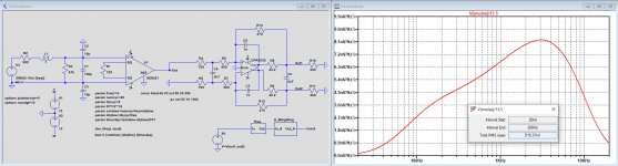
See example below.
Mechanical resonance will also take it's part, but it's obvious that to get an optimal FR, one has to tune the load resistance and the load capacitance in a real life situation.
In that light is making a calculation with an accuracy of 1e-10 rather pointless, sorry for that.
Hans
Attachments
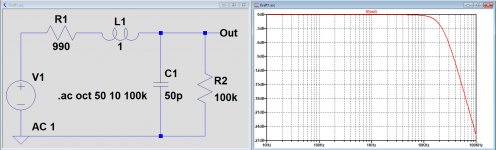
Your example shows that when you reduce the L/R time constant by using twice the normal load resistance, the -10 dB point goes to 40 kHz. It looks to me like the inductive and resistive effects dominate, although capacitance also matters of course.
I don't see the point in tuning the load resistance, especially not in simulation, when the cartridge manufacturer already recommends a certain value, usually 47 kohm. The manufacturer knows precisely what the mechanical transfer looks like and what effect the frequency-dependent ESR of the cartridge has.
Why don't you simulate your cartridge model with the load recommended by the manufacturer, so you will know what the electrical response (excluding the effect of the frequency-dependent ESR) is supposed to look like?
Last edited:
The manufacturer knows precisely what the mechanical transfer looks like and what effect the frequency-dependent ESR of the cartridge has.
I don't actually think they do though. They might have done in 1975...
Hi Hans,
Thank you so much for all your time! I've dropped the Xfrmr, must be a simulation artifact I`m seeing.
Been playing around with the Idea Marcel posted ("cold" electrical resistance). That does seem to make real difference.
I've based it on the attached paper and make a calculator in Excel. Sims included.
Worth it you think?
Attachments
Last edited:
You aren't. The ADC runs at a fixed rate and it's digitally filtered with some pretty steep filters to produce the required PCM output.
It's a personal decision, but worth checking the filtering you get for free. Single pole LPF is possibly all you need in the analog domain.
Sure, as always just 1 of many design decisions. I've always learned to limit the BW of an amp to what is needed, not more, not less.
But I`m not a Msc EE (actually dropped out before I got my Bsc EE 🙁). Maybe there is a good reason to extend the BW that I'm not familiar with?
There is an edge case on click reduction where having a wider bandwidth can help. This is of interest if you de-click pre-RIAA such as when archiving. There is little program material beyond 15kHz though...
This cold resistance topology is nice from a technological point of view and it was of some help in the past when low now noise was more difficult to achieve.Hi Hans,
Thank you so much for all your time! I've dropped the Xfrmr, must be a simulation artifact I`m seeing.
Been playing around with the Idea Marcel posted ("cold" electrical resistance). That does seem to make real difference.
I've based it on the attached paper and make a calculator in Excel. Sims included.
Worth it you think?
However with the current availability of super Op-Amps, noise is 10 to 15dB or more beyond the surface noise from the LP giving a S/N of 75dB-A or more.
With the arm in the air, there is no noise or hiss to be heard from the LS with such figures.
So there is a point where less noise makes no sense, and that is the case in your situation.
The 2 or 3dB gain in S/N with this technique is not bringing anything unless you like to explore new technical areas.
Only in case of loading the Cart with a much lower resistance to become less dependant on the capacity of the interlink, and at the same time making the load part of the Riaa curve, in those cases a cold resistance may help to recover the lost S/N by this lower load.
Hans
P.S. I will calculate the S/N in dB-A after Riaa correction and A-weighting for your situation, that will give you a solid base for further decisions.
As promised did I try to calculate the S/N for this amp.
Results were disappointing with ca. 68dB-A.
So I looked at the specs of the AD8429 and noticed that the current noise is way too high for a MM amp with 1.5pA/rtHz.
You will have to look for another amp, preferably Fet, but in any case for something below 0.3pA/rtHz.
Hans
Results were disappointing with ca. 68dB-A.
So I looked at the specs of the AD8429 and noticed that the current noise is way too high for a MM amp with 1.5pA/rtHz.
You will have to look for another amp, preferably Fet, but in any case for something below 0.3pA/rtHz.
Hans
So in post #107 you write it is useless to eliminate a noise current of sqrt(4 k T/47 kohm) ~= 0.5869 pA/sqrt(Hz) and in post #108 you recommend using an amp below 0.3 pA/sqrt(Hz)?
As promised did I try to calculate the S/N for this amp.
Results were disappointing with ca. 68dB-A.
So I looked at the specs of the AD8429 and noticed that the current noise is way too high for a MM amp with 1.5pA/rtHz.
You will have to look for another amp, preferably Fet, but in any case for something below 0.3pA/rtHz.
Hans
Hi Hans,
Yes noticed that, switched to the AD8421, has better current noise specs 200fA/rHz.
Marcel: Some measurements suggest 80-100k is a better load for a lot of modern MMs. Would that allay your concerns at all 🙂
It would reduce the noise current. It also makes it more difficult to make an amplifier that works well with any MM cartridge, because now you have to switch capacitance as well as resistance. Does anyone understand why these cartridges aren't optimized for 47 kohm, like they always used to be?
I'll get back to you on that. I have two MMs in my collection that are really happy into 47k. I remain unconvinced about the others. Take for example the Audio technica AT150 generator. It's only electrically 0.5dB down with 47K and 150pF., but how many people have only 150pF loading? Most have that in the cables alone and then another 200pF or so in the preamp.
Mark, just as a refence to compare your amp to commercially available amps.
Many manufacturers and reviewers specify S/N with the input shorted.
This gives of course super optimistic and misleading information, but anyhow a figure of 75dB-A is mostly regarded as very good.
In your case with the AD8421, S/N is 88dB-A with shorted input, showing that with the modern super Op-Amps a high S/N is very easy to achieve.
Hans
Hi Hans,
Thank you so much, I'll update my build with the latest insights.
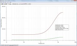
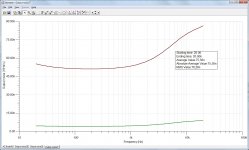
Right now I`m running with the AD8221, results are dissapointing especially w.r.t. 50Hz and harmonics. Noise is not great either but I think that is due to operating at low gain, should be fixed by the AD8421 circuit.
The 50Hz interferer is about 25dB above the noise floor (with a spray of harmonics visible also), do you think mounting the inamps in a little diecast aluminum box will make a difference?
PSRR is so high at these frequencies that the power supply can mostly be ruled out, so I guess this interference is picked up in the cables and/or on the PCB.
Thank you so much, I'll update my build with the latest insights.
Right now I`m running with the AD8221, results are dissapointing especially w.r.t. 50Hz and harmonics. Noise is not great either but I think that is due to operating at low gain, should be fixed by the AD8421 circuit.
The 50Hz interferer is about 25dB above the noise floor (with a spray of harmonics visible also), do you think mounting the inamps in a little diecast aluminum box will make a difference?
PSRR is so high at these frequencies that the power supply can mostly be ruled out, so I guess this interference is picked up in the cables and/or on the PCB.
Can you post the exact circuit that you are using at this moment.
Results compared to LTSpice simulations are usually very close.
And at what point did you measure THD and noise.
Maybe you can show the noise spectrum behind the AD8421, that could reveal something.
And you could temporarily try two 12V batteries to exclude eventual ground loops.
Hans
Results compared to LTSpice simulations are usually very close.
And at what point did you measure THD and noise.
Maybe you can show the noise spectrum behind the AD8421, that could reveal something.
And you could temporarily try two 12V batteries to exclude eventual ground loops.
Hans
Hi Hans,
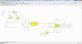
Running the AD8221 right now, not the AD8421. 6k8 gain set resistor, 47pF cap on the input and 23k5 from each input leg to gnd. So quite different from the new circuit.
All measurements so far with a focusrite 8i6 and inverse riaa filter, spdif back into the 8i6.
Not behind the PC right now, I'll post the schematic tomorrow
Right now I`m running with the AD8221, results are dissapointing especially w.r.t. 50Hz and harmonics. Noise is not great either but I think that is due to operating at low gain, should be fixed by the AD8421 circuit.
The 50Hz interferer is about 25dB above the noise floor (with a spray of harmonics visible also), do you think mounting the inamps in a little diecast aluminum box will make a difference?
PSRR is so high at these frequencies that the power supply can mostly be ruled out, so I guess this interference is picked up in the cables and/or on the PCB.
Is there a power supply transformer working on 50 Hz nearby? It is usually difficult to get RIAA amplifiers completely free of hum with a nearby supply transformer, although your balanced structure should help. Low-frequency magnetic fields are notoriously difficult to shield, but distance helps, keeping loop areas small helps and putting loops perpendicular helps. Electric fields can be shielded with anything that conducts well.
By the way, it is difficult to interpret what 25 dB above the noise floor means, as you are comparing a line spectrum to a continuous spectrum. What is your resolution bandwidth or DFT bin size?
Hi Marcel,
I'll run a swept sinewave measurent tomorrow with REW, and post more details. Kids are asleep now.
No big xformer in the preamp itself, a Meanwell switcher is providing the 5 and +/-15vdc.
I'll run a swept sinewave measurent tomorrow with REW, and post more details. Kids are asleep now.
No big xformer in the preamp itself, a Meanwell switcher is providing the 5 and +/-15vdc.
- Home
- Source & Line
- Analog Line Level
- Overload margin in Phono pre-amp