Your right, it is for the audiosector kit, same amp boards, different PSU board. It is always going to be a compromise with these boards connected in stereo. Audiosector try to create a single ground by connecting the two ground planes.
Connect the speakers and inputs as indicated on the amp.
Here is a different one that was proposed by me at the time.
Infinia, lets see your layout, please.
Connect the speakers and inputs as indicated on the amp.
Here is a different one that was proposed by me at the time.
Infinia, lets see your layout, please.
Attachments
Last edited:
that's the same thing , shows double wires but un-centralized at the PCB.
what wrong with balanced plus and minus supply pairs and a separate chassis wire for each PCB. like it was designed for?
what wrong with balanced plus and minus supply pairs and a separate chassis wire for each PCB. like it was designed for?
Infinia, lets see your layout, please.
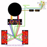
use twisted pairs 2 sets, one for + one for - for each amplifier. (keep star ground at the PCB)
add a chassis wire for class I to each amplifier at PCB ground. ( experts will keep floating from chassis if you have a rated XFMR and are double insulated on mains side. ) should your class I build develop a hum when connected to sources, insert 10-100 ohm on both input signal returns.
note use insulated bushings on all RCA and speaker connectors so only one chassis connection exists for each amp PCB
note 2 the chassis wires for class I says use wire rated greater than the fuse and must be securely connected E.g. crimped and lock washers etc
Last edited:
yes thank you, that is it
it's not the least # of wires , but it is rather simple and neat looking using pairs of wires.
I think you can use a separate chassis connection at the amp, so you don't have to run gnd wires so far. ( current is only under fault conditions > unlikely except for poor transformers and /or bad mains wiring techniques)
Last edited:
shouldn't be if your reference is the amp PCB ground plane and you don't connect another box at a different reference, in those cases I choose to increase signal level ground resistance slightly rather than solving ground loops with bus bars at the milli-ohm levels.
Last edited:
Not sure what you mean by "increase signal level ground resistance slightly". Are you talking about the Interconnect return or the IN GND - POWER GND connection?
I seem to remember that Peter of Audiosector shows a short thick grounding wire between the two Power Amp PCBs.
He then connects the middle of that short thick wire to everything else.
That is what appears in Mark's post61 drawing.
He then connects the middle of that short thick wire to everything else.
That is what appears in Mark's post61 drawing.
yes from post 59, on input signal returns insert a series resistor 10-100 ohm. probably the best place to hang it is at RF input filter oops there is none.
( should force any stray ground currents to take a "power path" instead. Eg usually neutral on mains )
( should force any stray ground currents to take a "power path" instead. Eg usually neutral on mains )
Hmm...I finally get around to trying to ground the things better, and I can't find good diagrams (NOT schematics) or verbal instructions on star grounding of these things.
Can someone please point me to a good diagram/picture?
And sumaudioguy, would you please, (this is the second time I've asked) stop hijacking my thread.
See my post #17 in this thread about proper grounding possibility.
I do not see how explaining the poor grounding and solutions to that poor grounding do not apply to your specific issues or how that is hijacking this thread. Infinia seemingly has almost no idea about real grounding but, has lots of time to add confusion. Mark appears to be the only other one here who does grasp grounding. Follow his advice.
I am sorry you do not like answers based in solid facts rather than feel good answer of myths. Not my problem. Do not insult me because of the bad feeling.
suma your trashing a commercial PCB ground adds nothing to the OP esp since you havnt shown any answers to "the problem" you supposedly identified. now your gonna tell him who's advice is better , again with zero basis? where are these "solid facts". LOL butt hurt much, please take a long hike\
its hilarious your unsolicited offer to help chipamp.com for free, I charge the big bux for my help for REAL problems, that should tell you something.
its hilarious your unsolicited offer to help chipamp.com for free, I charge the big bux for my help for REAL problems, that should tell you something.
Last edited:
seems you would have to try very hard to fry 4 LMs, IDK maybe one reason HW refuses to post pictures of the old test setup.
I have found most problems where I had mixed the power supply in with the audio signals. I did a USB mixer pcb and had 1 volt of hum on the output with input shorted !!
I redid the the pcb using a separate power supply circuit it had virtually no hum.
Having a separate power supply pcb is an excellent idea and should get rid of most hum loops.
The pcb should also be star grounded. Otherwise you can get output circuit modulating the input circuit causing havoc.
I redid the the pcb using a separate power supply circuit it had virtually no hum.
Having a separate power supply pcb is an excellent idea and should get rid of most hum loops.
The pcb should also be star grounded. Otherwise you can get output circuit modulating the input circuit causing havoc.
suma (clip) your unsolicited offer to help chipamp.com for free, I charge the big bux for my help for REAL problems, that should tell you something.
Infinia, you charge big bux huh? I bet you could be one of the engineers I fired for incompetence. It is very unlikely you get paid more than I do for engineering as I am well into six figures for that and can afford the 10 minutes it would take to fix this poor design. I have always considered audio a gentleman's business where fixing this board could help out a lot of people to better performance but, you seem to believe it is based in voting on the most popular opinion being the winner. A losers position needing to cling to the group of winning voters.
Hogwild, hope you get your board fixed and it works well for you. Oscillation in amplifiers is almost always one of two things, poor grounding scheme or lack of phase margin. Since we know the 3886 is not lacking phase margin poor grounding must be the culprit. See my post 17.
Last edited:
Bump! Still waiting for friend to come by to help me test amp properly grounded and/or with scope. Hope you all will not forget about my little thread. With much thanks again.
- Status
- Not open for further replies.
- Home
- Amplifiers
- Chip Amps
- Overheating and voltage issues