Hi everyone:
Electronics newbie here, with soldering skills, and some ability to use a meter. Assume nothing more in terms of knowledge. This stuff confuses the daylights out of me, so please be patient.
I finished soldering four Chipamp.com LM3886 amp boards and one pair of same company's PSU boards.
A friend helped me test three of the four amp boards and one of the PSU boards with a True RMS meter. Something is very wrong.
Transformer used: 300VA 18.00V dual secondary toroidal.
PSU board A: measured approx. 27V DC stable on both rails (under no load). OK, not too bad.
It appears that when the circuit is turned off then on again, we blew fuses.
First two amp boards (I soldered)
Amp board 1. Output 2V AC with no input.
Amp board 2. Output 5V AC with no input. Sometimes peaked as high as 16V AC with no load.
Frequency checks on amp board (2.) were all over the place.
Connecting either amp board to a speaker resulted in a bad hum which sounded like AC. However, the metered frequency was all over the place.
Amp board 2. heatsink got quite hot. It was only on for about 30 seconds, but took about 15 minutes to cool down.
Amp board 3. (soldered by someone else.) It seemed to display voltage measurement problems similar to the other two, but the heatsink remained cool. It also showed hum on the output. Third power on for that board blew a 2A fuse.
Scoping is not practical at the moment due to heat concerns after only a few seconds.
My friend also has only an analog scope, not one with storage.
Finally, both amp boards 1. and 2. have coaxial input wires, as recommended to me by people here. Amp board 3. has only single conductor wires for input.
Earlier posts I made told the story of how I started out with a solder process that didn't work right. Lead-free solder was just not
wetting. So I kept heating. Maybe I burned out some components?
Any help would be appreciated. So far, my journey with this has been long and painful.
Last edited:
You will need to provide some diagrams and images of your
LM3886 build. Nat Semi provide excellent instructions here:
http://www.ti.com/product/LM3886/technicaldocuments
Are you trying to run these all at the same time, from the one psu
or separately ? How much capacitance are you using on the rails?
Check your bridge rectifier if it is still alive, possibly the 300VA
transformer has taken out one or some the rectifier bridge diodes
a thing called in rush current. Take a measurement of AC content
on the supply without the amplifiers connected. 18VAC should be
25.45V DC, up and down a bit of course with mains voltage flucuations.
Cheers / Chris
Hi,
I agree with Chris, post some picts with both side of pcb.
Check R3 (amp board), page 8 :
http://www.chipamp.com/docs/User Guide - LM3886 Kit.pdf
Phil.
I agree with Chris, post some picts with both side of pcb.
Check R3 (amp board), page 8 :
http://www.chipamp.com/docs/User Guide - LM3886 Kit.pdf
Phil.
Few pictures would be good.
Short the input of the amp and check the output again.
You can check the psu part with scope if it is steady voltage without amps connected to it.
With shorted input there shouldn't be any AC at the output, or something is seriously wrong.
Short the input of the amp and check the output again.
You can check the psu part with scope if it is steady voltage without amps connected to it.
With shorted input there shouldn't be any AC at the output, or something is seriously wrong.
Last edited:
Hi there:
Thanks for the info. The boards are, as I said, stock Chipamp.com LM3886 boards. Nothing's been modded. Sorry, I really should've specified dual mono.
Not meaning to sound snide, but is there a need to post pictures if everything is stock?
My first posting about this project, including pictures, is here. They area lousy pictures, I think. Let me know if I should post better ones. In fact, I'll go to take some today, if I can.
http://www.diyaudio.com/forums/chip-amps/266577-help-troubleshooting-psus-chipamp-com.html
No need to read that entire post. It was newbie confusion and mega problems with lead-free soldering. In the end, I switched to leaded, but maybe I damaged some components?
levistubby: Oh darn, I can't believe I didn't think of specifying. Yes, everything came from the Chipamp.com kit. Absolutely 100% stock. I tested all the components before soldering. Did you mean I should test them again now?
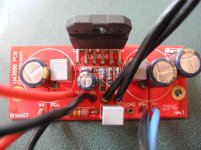
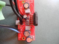
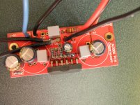
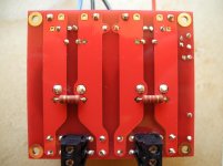
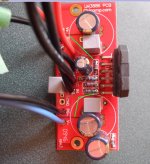
Here are some better pictures of the boards. Let's call the amp boards (acc. to who soldered them) b1, b2 and a1 for now. Let's call the PSU boards ps1 and ps2.
Here are some pics. In order, b1, b2, and ps1. I'll take photos of amp a1 and ps2 tomorrow and submit then as soon as I am able.
Here are some better pictures of the boards. Let's call the amp boards (acc. to who soldered them) b1, b2 and a1 for now. Let's call the PSU boards ps1 and ps2.
Here are some pics. In order, b1, b2, and ps1. I'll take photos of amp a1 and ps2 tomorrow and submit then as soon as I am able.
Attachments
-
 amp b1-top.jpg710.5 KB · Views: 320
 -
 amp b1-top-rotated.jpg756.9 KB · Views: 311
 -
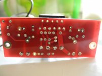 amp b1-bottom.jpg443.9 KB · Views: 303
 -
 b2-bottom.jpg707.2 KB · Views: 121
 -
 b2-top-upside down.jpg972.8 KB · Views: 297
 -
 b2-top-rightside up.jpg776.3 KB · Views: 298
 -
 ps1-top-front.jpg631.8 KB · Views: 109
 -
 ps1-top-rear.jpg649.4 KB · Views: 103
 -
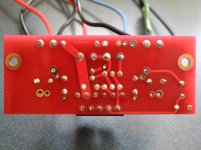
 ps1-bottom.jpg643 KB · Views: 111
Some of the solder joins on the board look like they need a little bit more solder. Other than that, everything looks in place. Double check the polarities on the capacitors to make sure everything is in the correct direction. If none of that seems to be working, then I would point to the transformer connections with those terminal screws. Make sure the screws are good and tight, and that the transformer leads are in order (one winding connected to one set, one connected to the other). If the transformer has more than two secondary coils, make sure that the secondaries are isolated (not soldered to other coils. I had similar symptoms to yours, except if it weren't for me noticing the solder melting on one of the terminals, I would have fried the rest of my power supply! Culprit was a third secondary soldered to my second secondary coil.  )
)
)Id much rather see the whole test set up. the PCB s/b OK since you built according to the kit. did you use volume control pot with DC block cap?
you used the coax is used improperly. use the center conductor to 'In" and outside shield to'SG'. don't need 2 coax cables for each amp.
please dress lead wires>
twist pairs of wires from the transformer outputs to the power PCB. 2 pairs.
\Twist pairs from power supply ( 2 pairs for each amp pcb.)
\Twist speaker output pair.
 , see post 3..
Problem1: The inverting input coupling cap has been bypassed (not employed) in those photos. To use it, that resistor next to it hooks up to the second via (the hole that is currently empty).
Problem2: Whatever went into the input, including DC, will be amplified. Also, the input cable needs hooked up correctly.
Problem2: Whatever went into the input, including DC, will be amplified. Also, the input cable needs hooked up correctly.
What a difference a few photo's can make.
Incorrectly installed R3.
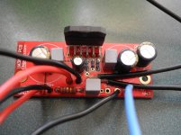
Badly soldered pins 1-3-5 LM3886.
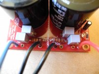
Non twisted pairs for input, output and PSU.
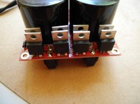
There are still many things that can't be seen. Heatsink, chassis, PE, grounding and transformer are all missing from the photo's.
Incorrectly installed R3.
Badly soldered pins 1-3-5 LM3886.
Non twisted pairs for input, output and PSU.
There are still many things that can't be seen. Heatsink, chassis, PE, grounding and transformer are all missing from the photo's.
Capacitors are definitely installed with polarity correct.
Using the two coaxial cables instead of one may be bad form, but I'm guessing it wouldn't cause the overheating/voltage problems mentioned, yes?
I have had problems with the transformer's secondary leadings popping out of the terminal blocks. Frankly, I'm surprised a kit of this quality doesn't use terminal blocks designed to hold wires from a 300VA transformer.
Before the last test, two of the transformer wires slipped out of the terminal block and touched the soldering iron holder, where of course, they shorted. I saw a tiny spark. The fuse blew. The LED on PS2 did not shine as brightly after that, so I may have damaged that or LED capacitor? This would not explain the lousy results on the first two amp board tests, however, which were done with PS1.
There is no volume contol circuit.
Would you please clarify the purpose of photographing the test environment. Everything is standard. I can assure you everything was hooked up acc. to theory, as it was done twice by me and once by my friend (who knows a lot more what he's doing than I ever will). Will photo if necessary, though.
OK, the above post may be largely irrelevant in terms of content now, because I took so long to edit it, that the Website timed out, and because I hadn't seen the posts on page 2 before I typed it. Consider this the more relevant post.
Capacitors are definitely installed with polarity correct.
So, according to the Chipamp.com manual (Page 8, section 1.7):
-For using the standard configuration, R3 is installed as shown on the right.
-For using the feedback capacitor, R3 is installed as shown on the left.
I obviously messed up installing R3. I did not notice the subtle difference between the two photos.
So, you're saying that I need to install a via between the pad closest to SG and the pad closest to the "R" in the word "R3" on the board, instead of removing and trying to reinstall another resistor? I will assume this should be the first repair I do?
Would my soldering R3 incorrectly likely have damaged any components on the boards?
Daniel, you said, "Whatever went into the input, including DC, will be amplified."
What did I do to create that? Is this a result of Problem 1, or it is something wrong I did separately?
If it's the second, how do I resolve that?
Daniel, you said: "the input cables need to be hooked up correctly".
Would you please be more specific. Remember, total newbie. I have no idea what that means.
Before the last test, on PS2, two of the transformer wires slipped out of the terminal block and touched the soldering iron holder, where of course, they shorted. I saw a tiny spark. The fuse blew. The LED on PS2 did not shine as brightly after that. Have I likely damaged the LED? What about the LED capacitor? No amp boards were connected at the time.
This, of course, would not explain the lousy results on the first two boards, which were done with PS1. Frankly, I'm surprised a kit of this quality doesn't use terminal blocks designed to hold wires from a 300VA transformer.
There is no volume circuit.
Last edited:
As i said in Post 2 Test the supply without the amplifier modules attached, Measure the AC content
this is to assess if there is a fault in the supply, there should be 25.45V DC +/-
and minimal AC content, less than 500mv given the size of capacitors, which are what value ?
See: Linear Power Supply Design I suspect you now have a diode or two not functioning, providing added AC content on the supply
Tidy up wiring, coax in particular should have a cable tie otherwise your day will be spent
continually repairing it.
Where is your heatsink ??
Where is your grounding ?
Install a L pad 2x resistors making a fixed but necessary minimum least for testing
volume control for each channel, 1k in series and 10k to ground will do
The LED will have a current limiting resistor, if it is now dimmer, likely you
have some AC content on the supply.
Fix the R3 issue.
Cheers / Chris
You amp is pretty clearly oscillating. It looks like pin 1 is not soldered on the top also and that plate through could be bad. Oscillation very likely caused by what I would consider one horrible grounding scheme.
Suggestion- Remove PG- and use a short piece of solid wire to loop between PG- and CHG. Solder PG- PG+ OG IG wires to this loop.
The way this is now there is no single point ground. Please recall it is the lowest impedance path and not the path or least resistance. Avoid ground planes for analog.
To do more cut about where the green lines are and run wires from the remaining holes between the caps over to the loop also. Isolate those ground current paths. You may have to run a ground to something else on the bottom but, cannot exactly tell by looking at your images. This puts all the high current grounds in one spot defining ground. Low current ground can use the remaining ground plane. The input ground and feedback ground should be very close together.
Attachments
Chris:
So, I asked a question earlier, about how to fix R3, and everyone threw in a ton of info. (which I can't keep up with, cause I'm a newbie).
Would you please comment on my question earlier about fixing R3? I need clarity. What's second nature to you guys is a foreign language to me. Worrying about ground planes is nice, but the closest one I can see is a 747 at my local airport.
- Status
- This old topic is closed. If you want to reopen this topic, contact a moderator using the "Report Post" button.
- Home
- Amplifiers
- Chip Amps
- Overheating and voltage issues