Chris:
So, I asked a question earlier, about how to fix R3, and everyone threw in a ton of info. (which I can't keep up with, cause I'm a newbie).
Would you please comment on my question earlier about fixing R3? I need clarity. What's second nature to you guys is a foreign language to me. Worrying about ground planes is nice, but the closest one I can see is a 747 at my local airport.
See the attached photo from the build manual. If using the feedback cap, install *over* the first via into the one closest to SG.
philfr previously pointed this out.
-Kev.
Attachments
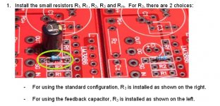
That's quite good! Yes, just move the resistor a little.See the attached photo from the build manual. If using the feedback cap, install *over* the first via into the one closest to SG.
philfr previously pointed this out.
-Kev.
But, the cap is too small for good sound. The associated cap should be at least 220uF (which doesn't come with the kit). I wonder what make&model (and voltage) Phil used for his? That'd probably be a good selection.
Yes, 220 uF is a good value..But, the cap is too small for good sound. The associated cap should be at least 220uF (which doesn't come with the kit). I wonder what make&model (and voltage) Phil used for his? That'd probably be a good selection.
http://www.diyaudio.com/forums/chip-amps/265827-lm3886-fullrange.html
An externally hosted image should be here but it was not working when we last tested it.
Phil.
Chris:
So, I asked a question earlier, about how to fix R3, and everyone threw in a ton of info. (which I can't keep up with, cause I'm a newbie).
Would you please comment on my question earlier about fixing R3? I need clarity. What's second nature to you guys is a foreign language to me. Worrying about ground planes is nice, but the closest one I can see is a 747 at my local airport.
Hi
R3 the leg of the resistor needs to be moved to the next hole
ie closer to the label marked SG. this is because you have the
capacitor installed.
To get resistors out that have been soldered in use solderwick
to remove the solder and create a clear hole again. If the
resistor is now too short, obtain another 1k resistor.
Heat sinking for the LM3886 and grounding is essential.
I am sure there will be instructions given with the kit you
purchased on the importance of grounding. An amplifier
ungrounded is very likely to be no better than a noise
source. And an amplifier without a adequate heat sink is just
asking for failure.
Grounding is a subject well worthwhile spending a
day or two getting used to. Thankfully it is well
documented :
http://www.diyaudio.com/forums/diya...udio-component-grounding-interconnection.html
Cheers / Chris
Last edited:
Yes, Yes, thank you guys. I get it. I get it. I just wanted to make sure I got it. The word "via" didn't seem appropriate, which is why I asked for clarification. I will likely try moving R3 lead/soldering in a new resistor, but I will have to find resistors first.
There is also some confusion because posts are showing up before my posts but after I posted.
I did use a heatsink, the implication seems to be because they are not in the pictures, that I didn't. I did for testing purposes. But believe me, with no input, the heatsink should have been much cooler, and one doesn't know what one's gonna get before one tests, especially as a total newbie.
So, all of you ground everything for the very first test, when there is no input signal, and no case? Reading on the Web, it seems tons of people off the forum test without grounding.
I took a few photos of the third amp board, a1, with the heatsink attached. I will post them soon, but not yet, so as to avoid more confusion.
While I await some resistors....
I have a question about the PS diodes (MUR860). I tested all 8 diodes on one ps board. I saw (in diode mode on DMM) ~ .394V in one direction, and a number that kept climbing in the other direction. Is that as expected with the diodes in circuit (power off, of course)?
Thanks.
I have a question about the PS diodes (MUR860). I tested all 8 diodes on one ps board. I saw (in diode mode on DMM) ~ .394V in one direction, and a number that kept climbing in the other direction. Is that as expected with the diodes in circuit (power off, of course)?
Thanks.
Last edited:
Sumaudioguy, the ground plane, at the top, is only used for power, output, bypass capacitors and zobel. The input and feedback returns (grounds) are on the underside. the two grounds connect at the output.
Thanks for the clarification. It is still a lousy grounding scheme. Here is what good grounding will do. http://www.diyaudio.com/forums/chip-amps/163385-so-just-how-good-can-chip-amp-9.html#post2149038
It is what it is, some good, some not so good, but it does work. Remember, partly due to this type of design, that the LM3886 is so popular.
Do you have a link showing the layout of your design?
Do you have a link showing the layout of your design?
why is it lousy did you study this one in detail?Thanks for the clarification. It is still a lousy grounding scheme.
seems good enough to me , or better than most.
the layout with a few parts mods, good enough to be even class A
and im not even sellin' anything
Last edited:
Uhh....guys, this is not a thread about how good the design is for the chipamp.com kits. Please help or move to another thread. I'm still waiting for an answer to my last question after 3 irrelevant posts.
While I await some resistors....
I have a question about the PS diodes (MUR860). I tested all 8 diodes on one ps board. I saw (in diode mode on DMM) ~ .394V in one direction, and a number that kept climbing in the other direction. Is that as expected with the diodes in circuit (power off, of course)?
Thanks.
You are probably seeing the filter caps charge up in one direction. As long as you're not seeing a direct short in either direction or an open in the forward direction, it's probably ok.
Hmmm...before I go making any more changes, I tested with my fairly knowledgeable friend tonight. All three amp boards (2 soldered by me, and one by someone else) had hum. Lots of it. Even with everything grounded. Yes, with heatsink. Yes, with all wires twisted. This was with using either ps board.
What's more, the amp board a1 (soldered by the other person) had the exact same hum, and votage problems, and it was wired without the capacitor Ci. To me, this suggests that the way I had soldered in R3 might not be the problem after all.
Finally, with 8 ohm speaker attached, one of the ps boards tested as having a higher voltage on one side than on the other side. ~25.5 vs. 26.5. This just gets weirder and weirder.
Anyone have any other suggestions I can try?
Last edited:
Again, we can not help without photo's. Even then it remains difficult to trouble-shoot at a distance, we are not really magicians. Did your friend have an opinion what may be wrong? Is the one board still getting very hot? Did you attempt to fix the bad soldering?
Ci sets the gain for DC to 1, where the AC gain is 33. So lets say that the offset at the input might be 10mV. With Ci the output offset is 10mV and without it would be 330mV. You are probably correct that the hum has nothing to do with Ci.
Ci sets the gain for DC to 1, where the AC gain is 33. So lets say that the offset at the input might be 10mV. With Ci the output offset is 10mV and without it would be 330mV. You are probably correct that the hum has nothing to do with Ci.
Hi,
Check solder for input, it does not look good..
Have you magnifying glass ?
Why did you use two shielded wire for input, how is it at the other end..
And please, post picts of your setup 😉
Phil.
Check solder for input, it does not look good..
Have you magnifying glass ?
Why did you use two shielded wire for input, how is it at the other end..
And please, post picts of your setup 😉
Phil.
Do you mean "grounding" as in audio grounding?..........................
So, all of you ground everything for the very first test, when there is no input signal, and no case? Reading on the Web, it seems tons of people off the forum test without grounding.
....................
or
do you mean "Earthing" as in Safety Earthing by using PE to Chassis?
took me to post82.Thanks for the clarification. It is still a lousy grounding scheme. Here is what good grounding will do. http://www.diyaudio.com/forums/chip-amps/163385-so-just-how-good-can-chip-amp-9.html#post2149038
Talking about measuring output impedance.
Is that correct?
Mark:
Not all three amp boards have bad soldering. The other two are quite fine, and exhibit exactly the same symptoms, so I'm not really convinced that is the problem.
Philfr: I am doubtful that the coaxial wire the way I soldered it is the problem. I say this because the third amp board used normal wire, highly twisted. It exhibited exactly the same hum. I used coaxial because in another thread, people on the forums here told me to.
AndrewT: audio grounding.
Hi,
Check solder for input, it does not look good..
Have you magnifying glass ?
Why did you use two shielded wire for input, how is it at the other end..
And please, post picts of your setup 😉
Phil.
Last edited:
uhh we need photos of the test set up as requested in post 10 and post 35.
Eg how you wired up everything including input to outputs. perhaps uses some undefined music source and speaker?
so far your complaints hum and occasional fuse blowing correct?
somehow the heat is fixed and power supply is still good.
Eg how you wired up everything including input to outputs. perhaps uses some undefined music source and speaker?
so far your complaints hum and occasional fuse blowing correct?
somehow the heat is fixed and power supply is still good.
- Status
- Not open for further replies.
- Home
- Amplifiers
- Chip Amps
- Overheating and voltage issues