sorry my good fellow but all the data i can find on the LM 3886 (regardless of manufacturer) all say the same thing. so if you can scan and upload the document you have that states that the suffix TF = tab isolated from circuit i can only go by published info.
assumptions can lead to erroneous conclusions not the sort of thinking that helps a troubleshooting situation.(and i apply this to myself as well)
sorry to once again hear things are bad for you.the hazing bit is a failed attempt at humour to try and highlight that in some instances lack of knowledge can become a big stumbling block to what we believe should be a relatively simple task like building an amp.
and if you think your position is unique PM me i will share some of the burdens and challenges i face perhaps unburdening yourself of some of your woes will free you to focus on finding your solution.
turk 182
Tests Using Scope for First Time
Hi everyone:
OK. My friend was here today as well and spent hours working on this. The results are as follows (This is him talking):
For now, we've only tested one power supply because of a learning curve with a new oscilloscope I just bought days ago. I bought this scope to help discover what the problem is.
Testing setup:
Power supply (PSU2) only, NOT connected to amp boards. Therefore, no load on the PSU.
The probe tip was connected to V+ with the probe alligator clip ground connected to PG+ .
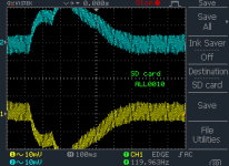
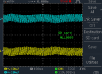
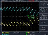
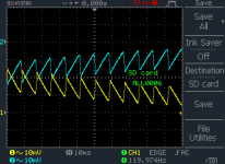
Likewise, for the second channel to V- and probe alligator clip connected to PG- . Using DC coupling on both channels, we observed one straight line trace for each side of the PSU. At PSU power on, there a quick offset from 0V to roughly the expected ~+-28V .
When we turned off the PSU, we observed a slow return of each side of the PSU to 0V . We believed this slow return to zero after the PSU was turned off was the capacitors discharging. We took no scope images at this point, as we believed it was as expected. We believed this was the right way to use the scope for this type of measurement. If it is not, please enlighten us.
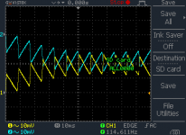
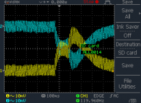
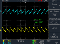
For the next test we used AC coupling on both channels. Probes were left as configured above. When using AC coupling, we observed a sawtooth-like pattern, when we were expecting something similar to a sine wave. The waveform observed is of low voltage, but does not seem like the expected appearance of ripple voltage. In addition, there is a shift and crossing over of the the two waves at various times, and other changes in the offset of these waves that we do not understand. Is it possible that we have not chosen the correct way to measure this with the scope using AC coupling?
(See below screenshots directly from scope).
Hi everyone:
OK. My friend was here today as well and spent hours working on this. The results are as follows (This is him talking):
For now, we've only tested one power supply because of a learning curve with a new oscilloscope I just bought days ago. I bought this scope to help discover what the problem is.
Testing setup:
Power supply (PSU2) only, NOT connected to amp boards. Therefore, no load on the PSU.
The probe tip was connected to V+ with the probe alligator clip ground connected to PG+ .
Likewise, for the second channel to V- and probe alligator clip connected to PG- . Using DC coupling on both channels, we observed one straight line trace for each side of the PSU. At PSU power on, there a quick offset from 0V to roughly the expected ~+-28V .
When we turned off the PSU, we observed a slow return of each side of the PSU to 0V . We believed this slow return to zero after the PSU was turned off was the capacitors discharging. We took no scope images at this point, as we believed it was as expected. We believed this was the right way to use the scope for this type of measurement. If it is not, please enlighten us.
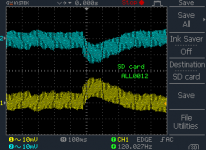
For the next test we used AC coupling on both channels. Probes were left as configured above. When using AC coupling, we observed a sawtooth-like pattern, when we were expecting something similar to a sine wave. The waveform observed is of low voltage, but does not seem like the expected appearance of ripple voltage. In addition, there is a shift and crossing over of the the two waves at various times, and other changes in the offset of these waves that we do not understand. Is it possible that we have not chosen the correct way to measure this with the scope using AC coupling?
(See below screenshots directly from scope).
Attachments
Hi,
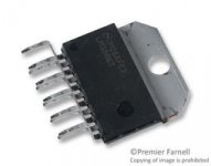
There are two type of LM3886. The LM3886TF it is totally encapsulated and do not require insulation and the LM3886T does require insulation. Both descriptions are shown in the last page of the TI LM3886 data sheet. I used both type chips.
There are two type of LM3886. The LM3886TF it is totally encapsulated and do not require insulation and the LM3886T does require insulation. Both descriptions are shown in the last page of the TI LM3886 data sheet. I used both type chips.
tauro 0221
the technote i'm referring to is on Page 2 (the last page of the document contains the usual legal mumbo jumbo) so your saying you've used both types mounted directly to the heatsink without mica washers and grounded the heatsinks?
hogwild
i don't see anything alarming in the posted scope traces.
the technote i'm referring to is on Page 2 (the last page of the document contains the usual legal mumbo jumbo) so your saying you've used both types mounted directly to the heatsink without mica washers and grounded the heatsinks?
hogwild
i don't see anything alarming in the posted scope traces.
Hi,
No,
I said that the LM3886T does require an insulation and the LM3886TF does not require insulation. The LM3886T you can see the bare metal with the hole to hold it to the heat sink. Attached it is a picture of the LM3886 and you can see it is completely encapsulated.
No,
I said that the LM3886T does require an insulation and the LM3886TF does not require insulation. The LM3886T you can see the bare metal with the hole to hold it to the heat sink. Attached it is a picture of the LM3886 and you can see it is completely encapsulated.
Attachments

tauro:
So, it is fairly normal for a pair of waveforms from Chipamp.com's PSU to display as sawtooth like, and for each to intermittently cross over into the opposite polarity?
Well, as you saw, turk192 seemed to disagree with me vehemently about the model number I used to refer to chips, so I just waited for clarification. I have used only the encapsulated ones that came with the kit, which apparently are the "TF" version.
Last edited:
i stand corrected. as i've not seen this type personally i was not aware of it existence.(and from what i can see there's a higher price tag that goes with these)
i was simply offering the possibility that neglecting to use insulating hardware could have inadvertently created a short. without seeing the amp in question and given all the difficulty the OP is having, a high resistance path/short to a grounded heat sink was not outside the realm of possibility, but this is not the case here.
i was simply offering the possibility that neglecting to use insulating hardware could have inadvertently created a short. without seeing the amp in question and given all the difficulty the OP is having, a high resistance path/short to a grounded heat sink was not outside the realm of possibility, but this is not the case here.
Hi,
On the scope pictures since the scope probe it is set to 10 mv you can see small ripples that are insignificant. Also to run the test you need to add some load to the PS so you can get a better idea what is going on with the PS.
On the scope pictures since the scope probe it is set to 10 mv you can see small ripples that are insignificant. Also to run the test you need to add some load to the PS so you can get a better idea what is going on with the PS.
turk182:
Glad we cleared that up. That last post may have sounded snide. I didn't mean to be snide, of course.
Tauro: Oh, I didn't know that either. I thought ripple was always supposed to be more of a sinusoidal shape.
Glad we cleared that up. That last post may have sounded snide. I didn't mean to be snide, of course.
Tauro: Oh, I didn't know that either. I thought ripple was always supposed to be more of a sinusoidal shape.
the smoothing capacitors charge up (voltage rises) during the diode on time which is very roughly 10 to 20% of the halfwave cycle duration.
Then the diode blocks reverse flow and the capacitor discharges (voltage falls) during the remaining 80 to 90% of the half wave cycle.
Look at your scope settings and use that to see what the variation is top to bottom of the ripple, Vpp.
Does it really swap polarity with the other?
Then the diode blocks reverse flow and the capacitor discharges (voltage falls) during the remaining 80 to 90% of the half wave cycle.
Look at your scope settings and use that to see what the variation is top to bottom of the ripple, Vpp.
Does it really swap polarity with the other?
AndrewT:
I have a few questions to ask which my friend helping me has posed, but I need to clarify them first. First, thanks again for sticking with us on this. I know the circumstances are trying.
Will have a few questions, then will run whatever tests you suggest next, but first just have to wait for my friend. For one thing, I don't want to blow up my new oscilloscope I just bought.
The AC coupling cap on the input is usually rated for over 400Vdc.
I should open mine up and look to see the rating.
If you use AC coupling and you never connect to mains, or similar high voltage, you cannot blow up your scope.
I don't know how they protect the amplifiers after the coupling cap, but they seem to be pretty robust and accept overload without any apparent damage. But just like a scale setting on a DMM, start at the least sensitive and work your way down the range till your trigger starts to detect a small signal.
AndrewT:
I'm not sure how to go about doing that. I'm starting to understand how to use the scope a little, without having my friend around.
However, what I noticed was that the two signals appeared to swap polarity briefly, but only when the timebase was very very low. I don't understand why it would appear that way, (or am I just misunderstanding it cause I'm a newbie?)
the readings do not swap polarity.
You must be using AC coupling to remove the DC bias.
You are displaying the AC VOLTAGES.
If you turn down the vertical scale so that you can display the DC+AC voltage and then attach the probes you will SEE that the polarities do not swap !
You must be using AC coupling to remove the DC bias.
You are displaying the AC VOLTAGES.
If you turn down the vertical scale so that you can display the DC+AC voltage and then attach the probes you will SEE that the polarities do not swap !
1) as stated above, image looks perfectly normal.
You set sensitivity to very high 10 mV, so, like the example of looking at a fly with a microscope, you see an ugly waveform and worry, but ripple value is actually minuscule, so don't worry.
Don't know what your actual problem is and won't read 100 posts to find it,but what you show us here is definitely not a problem.
2) ripple waveform, as stated by Andrew, is a sawtooth, showing relatively fast charging and slower discharging.
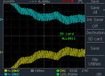
3) the first set of images is swept fast, 10ms is stated, and you can clearly see sawtooth waveform; the second set is swept 10X slower, 100 ms is indicated, so waveforms are still properly displayed, but so crammed together that *we* can't "separate" them and they blur into an illuminated "ribbon" .
Now we have a clearer view as of how average voltage changes with time.
You seem to be turning supply on and off, and/or loading/unloading it, in that case average voltage will change.
Even if "DC" so in theory it should "not" be shown, changing DC IS one form of AC , or you can say that it has some AC component, it WILL go through the coupling cap, you can also see it as "VERY slow AC" , point is that varying DC value will appear on the screen, but its waveform will be percieved as shifting the ripple baseline, you will see the "ribbon" twisting up or down, which is wat's actually happening at that moment.
But that both ribbons cross paths does not mean that that average DC voltage "inverted" , that -V became more positive than +V and viceversa, all it means is that dropping +V became less positive than some earlier value , -V did the same but going the other way, and that is accurately shown on the display.
If you want a Math/Physics explanation without the actual formulas, I'm more interested in your understanding the concept than actual numbers, an "AC" scope is actually a "DC scope with a blocking cap in series" , that coupling cap in series with the scope input impedance forms a "Differentiator" , it will let the Voltage *variation* through, which will be shown, in this case by tilting both ribbons down and up respectively.
They seem to cross, simply because scope sensitivity is high and they are **displayed** very close for your convenience, ribbon to ribbon distance does not mean any actual voltage, they are separated by an arbitrary value only so both neither superimpose or are outside the screen.
Scopes always show the truth , but it's up to us to understand the meaning of what we nsee.
Agree that sometimes it seems to be counter intuitive, but after some time it "clicks" in our minds.
So good luck with your troubleshooting, remember sometimes we get data from the measuring instruments but *we* need to process it.
You set sensitivity to very high 10 mV, so, like the example of looking at a fly with a microscope, you see an ugly waveform and worry, but ripple value is actually minuscule, so don't worry.
Don't know what your actual problem is and won't read 100 posts to find it,but what you show us here is definitely not a problem.
2) ripple waveform, as stated by Andrew, is a sawtooth, showing relatively fast charging and slower discharging.
3) the first set of images is swept fast, 10ms is stated, and you can clearly see sawtooth waveform; the second set is swept 10X slower, 100 ms is indicated, so waveforms are still properly displayed, but so crammed together that *we* can't "separate" them and they blur into an illuminated "ribbon" .
Now we have a clearer view as of how average voltage changes with time.
You seem to be turning supply on and off, and/or loading/unloading it, in that case average voltage will change.
Even if "DC" so in theory it should "not" be shown, changing DC IS one form of AC , or you can say that it has some AC component, it WILL go through the coupling cap, you can also see it as "VERY slow AC" , point is that varying DC value will appear on the screen, but its waveform will be percieved as shifting the ripple baseline, you will see the "ribbon" twisting up or down, which is wat's actually happening at that moment.
But that both ribbons cross paths does not mean that that average DC voltage "inverted" , that -V became more positive than +V and viceversa, all it means is that dropping +V became less positive than some earlier value , -V did the same but going the other way, and that is accurately shown on the display.
If you want a Math/Physics explanation without the actual formulas, I'm more interested in your understanding the concept than actual numbers, an "AC" scope is actually a "DC scope with a blocking cap in series" , that coupling cap in series with the scope input impedance forms a "Differentiator" , it will let the Voltage *variation* through, which will be shown, in this case by tilting both ribbons down and up respectively.
They seem to cross, simply because scope sensitivity is high and they are **displayed** very close for your convenience, ribbon to ribbon distance does not mean any actual voltage, they are separated by an arbitrary value only so both neither superimpose or are outside the screen.
Scopes always show the truth , but it's up to us to understand the meaning of what we nsee.
Agree that sometimes it seems to be counter intuitive, but after some time it "clicks" in our minds.
So good luck with your troubleshooting, remember sometimes we get data from the measuring instruments but *we* need to process it.
AndrewT, JMFahefy:
Thanks! Great explanations from both of you. I understand at least part of this, and this is what was my guess before you answered.
At no point did I turn the PSUs off during testing-they always remained on with no load attached. I assume this still makes sense, cause it's only visible at such a high "resolution" that it wouldn't have much effect on an audio signal, right?
Just checking...
The ripple current on the supply rails does affect the audio amplifier.
It's why we put in some smoothing capacitance.
The sharper the sawtooth the higher the proportion of high frequencies.
The more rounded the sawtooth, the lower the HF content of the ripple.
The amplifier has some Power Supply Ripple Rejection (PSRR). This varies a lot between amplifier topologies. Many can be good to excellent at rejecting 50/60Hz. Many can be bad to very bad at rejecting HF (the sharp parts of the sawtooth).
At quiescent for a ClassAB amplifier the ripple is least. i.e. when the amplifier is quiet, we don't hear the ripple at the speaker. The amplifier manages to reject the small amount of quiescent ripple.
At higher power the ripple increases. Now the loud audio output masks the ripple that leaks through to the speaker. FFT shows this effect and how bad it gets.
Our ears seem only to pick up the worst effects. The smaller effects seem to be more subtle. That may expalin why different listeners hear differences in sound quality.
Ripple and PSRR are very important to what comes out of the speaker.
Agree and add: even with the best ripple rejection amp in the Universe, once you start playing it LOUD and some peaks clip (since peaks can *easily* be 20dB above average volume), then ripple appears in the output, and in the worst way, not only "mixed" with the output signal but *modulating* it.
I never cease to be amazed about emotional discussions/arguments here about -100dB or better distortion components, when this GROSS effect is ignored, not even mentioned or considered.
Oh well.
I never cease to be amazed about emotional discussions/arguments here about -100dB or better distortion components, when this GROSS effect is ignored, not even mentioned or considered.
Oh well.
- Status
- Not open for further replies.
- Home
- Amplifiers
- Chip Amps
- Overheating and voltage issues