I see a (quite new) Studer schematic (service manual).
The phone amplifiers ware made (around) NJM4560.
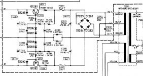
The power supply's ware SMPS and only small signal stages were powered from a linear (some xxx1117 regulator) but all stages were true differential.
The phone amplifiers ware made (around) NJM4560.
The power supply's ware SMPS and only small signal stages were powered from a linear (some xxx1117 regulator) but all stages were true differential.
There are tons of manual for those studers...as there were several versions too.it took me an hour to download some of them...but i couldn't find the headphone's module schematic yet.
I got very interested in the schematics attached in post #294.although i've downloaded about 10 studer partd of those manjuals i couldn't find the actual headphones amp, but i found some related schematics.
The one in the last of the six, is certainly a best.
With the right setting of current made by the two CCS thru the base spreader, this must give an outstanding low distortion amplifier.
Provided, the base spreader transistors and output transistors are thermally coupled, thermal stability is rock solid.
Studer or Neve were the leading figures of the whole recording industry...you can't ignore them.
Here's one more from a810 manual.they forgot the 0.1 ohm resistor in paralel with the 68nF cap to the ground from the speaker out.
Here's one more from a810 manual.they forgot the 0.1 ohm resistor in paralel with the 68nF cap to the ground from the speaker out.
Attachments

Last edited:
What you didn't mention is...
Manufacturing corporations buy and sell in quantity.
Of course the DIY'er pays more for say, a single high quality potentiometer.
When corporations order perhaps thousands - at discounted bulk quantities.
I know that. I buy some stuff in bulk too, but not expensive potentiometers. I might buy 25 of a resistor value I use a lot; not thousands at a time.
There are significant saving to be had when ordering a thousand units at a time, no doubt.
Studer or Neve were the leading figures of the whole recording industry...you can't ignore them.
Here's one more from a810 manual.they forgot the 0.1 ohm resistor in paralel with the 68nF cap to the ground from the speaker out.
I wouldn't like a 0.1 ohm across any speaker O/P I have.
Hi ! thanks a lot again for the very valuable advice.
I think that many British manufacturers had the right approach in the early '80s. No tone control ... just a inputs selector and a volume and the power switch. And i understan this paid in terms of sound quality.
I am not against eq ... problem maybe it is to do it right ? i do not know. It is complex.
And moreover often a real preamp stage is not needed at all in an integrated. Preamps are for people who wants to play with cables, different power amps ... like me i mean 😱
Placing a very good passive attenuator of the right value makes a very good power amp a great integrated.
This is what i would like to do if i cannot be able to make a decent line preamp. This story of the line preamp is obsessing me. Very much.
I've got to warn you - "passive" preamps can introduce distortion if not carefully implemented. Conventional wisdom says use the lowest value practical to mitigate high frequency rolloff from cable capacitance. But that lower impedance can affect low frequency rolloff of the source - any source should drive 10K with no problem but specs are almost always stated for 47K input impedance, the industry standard.
In my opinion, nothing beats a buffered volume control. 47K input impedance, 47 or 100 ohm output impedance, doesn't vary at all with volume control setting. Plus you can drive long cables with no ill effects. It covers all the bases but "purists" hate it. They drone the mantra of distortion from op amps while ignoring the real world distortion from sloppy application of their passive preamp.
I've got to warn you - "passive" preamps can introduce distortion if not carefully implemented ... In my opinion, nothing beats a buffered volume control. ...
thanks a lot again for the very valuable advice. I think i will indeed end with something like what you propose ... i like the idea of a volume control stage insensitive to what is before and after it. Able to drive properly any power amp stage ...
Now the issue becomes ...
1) which buffer. Just a single op-amp ?
2) taking care a little more of the power supply ?
i read among other things, but i do not know if it is true or not, that what could really draw back in terms of sound quality an opamp based preamp are not the opamps but the power supply used to feed them ?
Usually they are realized with fixed voltage regulators ... and these could be not the optimal choice ? better regulator circuits realized with discrete parts ?
a good and huge source of schematics for this family of regulators can be TOTL preamps of the late '70s and early '80s ...
my guess is that at the time fixed voltage regulators were less available ? so designers had to cope with the issue and someone did a great job maybe ?
what is handy sometimes have other issues ... for instance their PSRR at higher frequencies collapse ... ok there is also the PSRR of the op-amp to take into account
But i like the idea of discrete regulators ... a lot
I end saying that this issue of the discrete regulators is very important to me. I have a preamp said to have a quite low distortion and good driving ability
But i get some noise ... the power supply is made with a pair of 24V fixed regulators
Maybe with a better regulator stage it flies to the moon ? if so ... i could finally start enjoying music ... i am sure of that
Last edited:
So many schematics so little time.
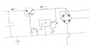
yes indeed. I will search in the proper section to understand how much fixed voltage regulators are popular. Maybe i was putting the blame on innocent opamps ... i am attaching an example. I guess that with different zeners could work also for -/+24V as well
I am seriously thinking about trying it ... 😱
Attachments
About this regulated PSU be aware of:
There is not ouput protection. A short is fatal.
The voltage is not accurate from zener diodes that have not so good accurate voltage.
LM317 LM337 are popular regulators one can adjust with two resistors.
There is not ouput protection. A short is fatal.
The voltage is not accurate from zener diodes that have not so good accurate voltage.
LM317 LM337 are popular regulators one can adjust with two resistors.
he moved the subject here:
https://www.diyaudio.com/forums/power-supplies/359652-fine-ic-voltage-regulators.html#post6329244
https://www.diyaudio.com/forums/power-supplies/359652-fine-ic-voltage-regulators.html#post6329244
About this regulated PSU be aware of:
There is not ouput protection. A short is fatal. The voltage is not accurate from zener diodes that have not so good accurate voltage.
LM317 LM337 are popular regulators one can adjust with two resistors.
Thanks ! just to complete information it is part of the power supply of the old Onkyo P-303 preamp, dated 1979 ? as mentioned above at the time there were not many monolithic voltage regulators. So the discrete solution was mandatory. I moved the question in the power supplies section for opportunity
Some interesting discussions are coming out ... with someone mentioning the importance to have a good response to current transient 😕 and a high PSRR at higher frequencies. I am sure that some specific circuits can improve both also for the LM317.
Moreover given that you mention a not so good accurate voltage from zener diodes, could the LMxxx be used instead as voltage reference and the bjts as current devices ? i mean with the LM out connected to the bjt base 🙄
yes.i built something like this 15 years ago for a friend to supply a radio station:
12V 15A voltage regulator
12V 15A voltage regulator
yes.i built something like this 15 years ago for a friend to supply a radio station:
12V 15A voltage regulator
Thanks ! i guess this is to increase the current out ? look instead at the schematic attached ... the LM part acts only as a voltage reference driving the bjt base
No need to source big current only stable voltage The current will be provided by the bjt instead
can it work ? that is the question 😱
I have looked in the LM datasheet but i did not find a similar schematic ... so i guess it cannot work
Attachments
Last edited:
.............................................................
I feel the need to ask you a rather phylosophical question:
do you really need to urge to be absolutely original?
I feel the need to ask you a rather phylosophical question:
do you really need to urge to be absolutely original?
Last edited:
.............................................................
I feel the need to ask you a rather phylosophical question: do you really need to urge to be absolutely original?
call it thinking differently ... or creative engineering
anyway ... can it work ? maybe not ...
it doesn't work well...is this a good enough answer for you?if not, it means that you need to read some books...
it doesn't work well...is this a good enough answer for you?if not, it means that you need to read some books...
More than enough ... i will stick with tested schematics Still i will try it not that difficult with some patience Very few parts are needed 😉
1) which buffer. Just a single op-amp ?
2) taking care a little more of the power supply ?
1) Op amp driving the input, op amp driven by the wiper of the potentiometer on the output. So two op amps. You can configure the output for gain if desired; I built a board with jumpers (like you find inside computers) so the gain can be changed from 1.5 to 2.5. (I leave it on 1.5.) Even with a large potentiometer like the Alps Blue Velvet you can build a very small board. Add a header and wire harness (I save all headers and wire harnesses from equipment I scrap) and you have a very professional looking module.
2) Yes, quiet power supply is always an improvement. LM317/337 has rising output impedance with frequency. So does 7812/7912. This is where bypassing comes in. You deal with ripple before the regulators with an LC network. Use large capacitors (I use 2200 uF/35V x 4 and 100 ohm 1 watt resistors x2).
You have to have a capacitor on the output. This deals with the rising impedance with frequency. And you have to have local (on board) bypassing, including both electrolytic capacitors (22 uF is fine for a couple op amps) and and high Q ceramic or film capacitors right on the power supply pins of the op amps. Believe me, these details make for a very low noise floor, and reduce distortion too.
There's discrete power supplies and fancy shunt regulators for line level circuits. That's a topic on its own. I suggest you build a practical and conventional circuit first. I never mess with stuff like this; optimizing conventional regulator circuits the easy way (some would call it brute force) works very, very well.
call it thinking differently ... or creative engineering
anyway ... can it work ? maybe not ...
Learn the basics first. Understand and master classic circuits. Learn to optimize them. Getting them to work better is a worthy goal and is an accomplishment in its own right.
- Home
- Member Areas
- The Lounge
- Overengineering in audio equipment