Trying to understand control amplifiers you also need to understand that they came in moment when Vinyl was the king of the hill so the needed to be able to adapt very high dynamc inputs to whatever amplifier you're using. You might need to read this topic:
Overload margin in Phono pre-amp
Overload margin in Phono pre-amp
My phono stage can take more than 2V of overload... the record is ~ 5mV from my cartridge... Good enough headroom I think 🙂
most valve phono preamps can take that ... my last preamps were based on D3A with -1.2v bias at 16ma anode current so that would be the theoretical limit, but some valves can take also grid currents so will accept even higher inputs with significat , but pleasing distortions . 0.5v is the absolute max imput needed for a phono preamp but 0.35v was the max solid state overload input and it was good enough.
No reason you couldn't go hybrid I guess... Tube voltage gain, MOSFET current buffer. I would use triodes because they are cheaper than heatsinks and they are more linear than MOSFETs.
Thanks for the valuable advice. Maybe i am overestimating the linearization power of NFB 🙁 i mean ... like NFB the cure of all diseases ...
and how does it sound ? do you have the schematic maybe ? 😱 maybe it could be scaled down for line stage duties ... 🙄I also have a thing for depletion mode parts because the can be "cathode biased" 🙂
But as a source follower, it doesn't seem to matter much -- I'm listening to a hybrid SE MOSFET amp right now that is set up as a source follower.
NFB can correct errors, but isn't it better if there aren't errors in the first place? NFB has a certain speed to it. In theory, if there's a fast enough transient, NFB will correct it after it's already gone. I guess that comes down to slew rate etc.
Don't get me wrong - I use gNFB in all of my tube power amps, but I don't use gNFB in line/phono/headphones... Even my SE MOSFET amp has no gNFB loop in it. Just local FB because of unbypassed cathode resistors.
My take on an RIAA stage... Forgive me if I already posted it.
Don't get me wrong - I use gNFB in all of my tube power amps, but I don't use gNFB in line/phono/headphones... Even my SE MOSFET amp has no gNFB loop in it. Just local FB because of unbypassed cathode resistors.
My take on an RIAA stage... Forgive me if I already posted it.
Attachments
NFB can correct errors, but isn't it better if there aren't errors in the first place? NFB has a certain speed to it. In theory, if there's a fast enough transient, NFB will correct it after it's already gone. I guess that comes down to slew rate etc.
Don't get me wrong - I use gNFB in all of my tube power amps, but I don't use gNFB in line/phono/headphones... Even my SE MOSFET amp has no gNFB loop in it. Just local FB because of unbypassed cathode resistors.
My take on an RIAA stage... Forgive me if I already posted it.
First of all ... we have a different opinion on what is simple 😱😀
Second ... i am a SW guy If a circuit passes a SW test very well it cannot be bad SW signal is a beast of a signal ... i like when i get at the ouptut a signal very close to the test signal sent in ... i like that very much indeed.
I am sure that the FB can be implemented with no lag let's say ... connecting the pin out with the controlling pin physically ... even with no resistor in between (a buffer)
I am attaching what i mean
Attachments
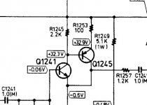
Since I have little knowledge of SS, I can only guess the NPN adds LOTs of gain, and the PNP works in anti-phase against it?
My knowledge is mostly limited to NPN type devices I'm afraid... I'm still learning about PNP -- I'm just starting to branch into SS from tubes.
How about this for an example of simple != better? Just saying, rearrange the parts (and vaules/voltages), and replace the 2N3904 with a 6SN7 and voila! Simple AND good 🙂
Last edited:
Things get a lot simpler when you think in terms of Error Prevention instead of Error Correction.
Trying to understand control amplifiers you also need to understand that they came in moment when Vinyl was the king of the hill so the needed to be able to adapt very high dynamc inputs to whatever amplifier you're using. You might need to read this topic:
Overload margin in Phono pre-amp
i see. Still companies produce and sell line stages ... i have to control the volume at some point in the chain. I just had issue with gain ... so i am thinking about the diy solution to set the gain as i like
Now as soon as i turn the knob the volume is always too high 🙁
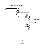
Ok... post the schematic of _what you're using_ and we can see how to reduce gain...
Simplest is this though - the pot is the existing pot in the line stage:
Adjust R values as needed for SS. Probably just divide by 10.
Simplest is this though - the pot is the existing pot in the line stage:
Adjust R values as needed for SS. Probably just divide by 10.
Attachments
Last edited:
well my knowledge is like zero ... the only thing i know is that that circuit works because it is a commercial unit ... and said to sound quite decentSince I have little knowledge of SS,
My take is that a part of a good thing cannot be that bad ... like in a hen
good question. i understand that is a kind of NFB just thatI can only guess the NPN adds LOTs of gain, and the PNP works in anti-phase against it?
too high Zout maybe ? regarding single device stages i am fixed on the BOZ preamp by Nelson PassMy knowledge is mostly limited to NPN type devices I'm afraid... I'm still learning about PNP -- I'm just starting to branch into SS from tubes.
How about this for an example of simple != better? Just saying, rearrange the parts (and vaules/voltages), and replace the 2N3904 with a 6SN7 and voila! Simple AND good 🙂
I have already one ... in the weekend i will look for it 😱 if i find it i will post some pictures. My intention is to lower the gain and use a smsp 48V that should be arrived soon. I decided to try an smps for some reasons:
1) is very cheap and small, therefore it can be placed inside the case
2) i have been told that most of its noise (around some 100-200mVp-p) is mostly located outside the audio band (hope that if not i will have to switch to linear psu)
The BOZ is very good as a power supply noise tester because all the noise incoming is available at the output and so amplified by the power amp.
If i will get silence ... well that will be a great day. I feel it.
Thanks a lot for your sharing of very valuable information.
Have a nice day 🙂
Last edited:
Good call on SMPS. If you find noise, RC or LC filtering will snub it. The system I'm listening to right now is powered by an ATX computer supply. Everything gets boosted from 12V. Silent power. Obviously zero hum. More efficient, too.
See this: Kanged switching power supply for a tube amp. EDIT: Those we're the days... Both the PSU and the amp it powered have been scrapped, but new versions were built!
There have been some mods but the general idea is the same.
See this: Kanged switching power supply for a tube amp. EDIT: Those we're the days... Both the PSU and the amp it powered have been scrapped, but new versions were built!
There have been some mods but the general idea is the same.
Last edited:
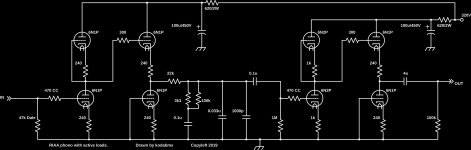
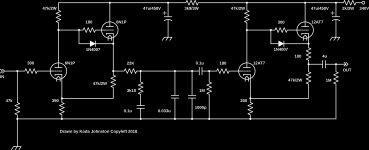
You riaa needs great care with heater noise and is also overengineered...NFB can correct errors, but isn't it better if there aren't errors in the first place? NFB has a certain speed to it. In theory, if there's a fast enough transient, NFB will correct it after it's already gone. I guess that comes down to slew rate etc.
Don't get me wrong - I use gNFB in all of my tube power amps, but I don't use gNFB in line/phono/headphones... Even my SE MOSFET amp has no gNFB loop in it. Just local FB because of unbypassed cathode resistors.
My take on an RIAA stage... Forgive me if I already posted it.
Compare it to luxman design and see what you don't really get about the feedback benefits! The headphones diamond buffer which is a discrete version of LH0002 is outside of any feedback network though...
I already built the most complicated hybrid phono designs with no global feedback, but using a huge amount of components to liniarize a valve preamp isn't really genious...
Attachments
What heater noise? They run on the same 12V (15mV ripple) as the rest of the system... Also how is it over-engineered? The active loads seek to linearize the circuit as you said, but I don't see a lot of components. They also move waste heat above the chassis allowing for a smaller footprint..
Would you prefer this?
Would you prefer this?
Attachments
Last edited:
Good call on SMPS. If you find noise, RC or LC filtering will snub it.
This is a very good news. The preamp is class A and every channel draws about 40mA at 60V. I understand that LC are better than RC ? the search for a suitable schematic is already on but first ... i have to find the corpse.
May i ask how ? 😱 a dc-dc step-up converter ?The system I'm listening to right now is powered by an ATX computer supply. Everything gets boosted from 12V.
Thanks a lot indeed. Not that a linear psu was out of my ability ... but this smps come already encapsulated even in plastic case (i.e. isolated) and i guess also shielded.Silent power. Obviously zero hum. More efficient, too.
See this: Kanged switching power supply for a tube amp.
EDIT: Those we're the days... Both the PSU and the amp it powered have been scrapped, but new versions were built!
There have been some mods but the general idea is the same.
I just hope that the residual noise will be above 14kHz ... 🙄
This is a very good news. The preamp is class A and every channel draws about 40mA at 60V. I understand that LC are better than RC ? the search for a suitable schematic is already on but first ... i have to find the corpse.
Class A has no overall current swing, so it's easier to filter for. RC filer is cheap and works well... LC even moreso, but you have to find the "critical" values otherwise it doesn't really work.
May i ask how ? 😱 a dc-dc step-up converter ?
Yes. I linked it earlier.
Thanks a lot indeed. Not that a linear psu was out of my ability ... but this smps come already encapsulated even in plastic case (i.e. isolated) and i guess also shielded.
I just hope that the residual noise will be above 14kHz ... 🙄
It will be above 14kHz unless it's a real slice of crap.
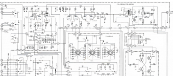
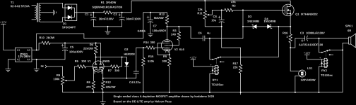
For your pleasure: I spoke about the SE MOSFET amp I'm listening to... Here's the recipe (schematic). Yes, LS1 is a pair of 200W incandescent light bulbs acting as the load resistance... It could be replaced with 18R/100W resistor, but more expensive that way. And this way you get free light!
Attachments
Last edited:
there's no great benefit in reducing heater's ripple when the cathode -fillament current leak is in the order of picoamperes.The only way to escape filament noise entirely is to lift it above cathode potential by 30...50v depending on Vkf max to cancel that current leak.You can do that with the heater supplied by AC voltage with same results.What heater noise? They run on the same 12V (15mV ripple) as the rest of the system... Also how is it over-engineered? The active loads seek to linearize the circuit as you said, but I don't see a lot of components. They also move waste heat above the chassis allowing for a smaller footprint..
Would you prefer this?
well that 1...10 picoampere leaking current is 100...1000 times lower than microamperes which is the gate bias current...so it's a -40 db...-60db noise superimposed on 0db signal...that's a lot!
- Home
- Member Areas
- The Lounge
- Overengineering in audio equipment