OK. I will try to make similar to Mercury board. However the stack height will be increased. The printed circuit board with my transformers will raise the Buffalo board 15-20 more millimeters higher than it is positioned now on the Mercury board. Will this not be a serious problem? ..
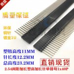
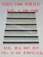
As shown in the photo, the length of the pin header can be up to 70mm, so just a height of 15-20mm will not be a problem.
The size of my DAC case is 160mmX160X90mm, which probably accommodates Buffalo and MERCURY, so there is no space to accommodate more PCB boards in parallel.
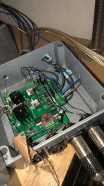
I bought a transformer from China, but the sound was terrible, so someone suggested that I should connect the transformer to the output of MERCURY. What is the difference between the transformer directly replacing MERCURY or connecting the transformer to the output terminal of MERCURY?

The size of my DAC case is 160mmX160X90mm, which probably accommodates Buffalo and MERCURY, so there is no space to accommodate more PCB boards in parallel.

I bought a transformer from China, but the sound was terrible, so someone suggested that I should connect the transformer to the output of MERCURY. What is the difference between the transformer directly replacing MERCURY or connecting the transformer to the output terminal of MERCURY?
OKAs shown in the photo, the length of the pin header can be up to 70mm, so just a height of 15-20mm will not be a problem.
Good suggestion as it is VERY different conditions for both the DAC and the transformer you bought.I bought a transformer from China, but the sound was terrible, so someone suggested that I should connect the transformer to the output of MERCURY. What is the difference between the transformer directly replacing MERCURY or connecting the transformer to the output terminal of MERCURY?
You mean, I should try to connect bisesik's transformer to the output of Mercury first when I buy it?
No. "After" Mercury and "Instead" Mercury: are two very different situations for two different types of transformers. I offer version "Instead".
See the first post please, your version is 2 coils.
PCB CAD file, gerber files will be available for free. Price for the finished board is unknown yet but something between $20 - $40 + trafos cost I think...
PCB CAD file, gerber files will be available for free. Price for the finished board is unknown yet but something between $20 - $40 + trafos cost I think...
What is the approximate temperature of the soldering iron when the soldering transformer is on the PCB board?
less than 250°C please
FYI: there is a possibility to use receptacles instead of soldering ("tube-socket-style") as well. gold-plating are on both transformer's pins & PCB receptacles.
FYI: there is a possibility to use receptacles instead of soldering ("tube-socket-style") as well. gold-plating are on both transformer's pins & PCB receptacles.
Last edited:
Done.
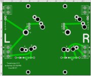
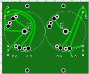
Here is the PCB version of "Transformers I/V stage" for Twisted Pear Buffalo III SE PRO.
The dimensions are based on the Mercury board, but I slightly shortened the width to fit 100 mm limit for reducing the cost of ordering at a PCB factory.
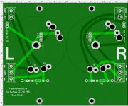
Gerber/CAD files are in the zip-file.
View attachment BuffaloIIIsePRO_trafos.zip
Here is the PCB version of "Transformers I/V stage" for Twisted Pear Buffalo III SE PRO.
The dimensions are based on the Mercury board, but I slightly shortened the width to fit 100 mm limit for reducing the cost of ordering at a PCB factory.

Gerber/CAD files are in the zip-file.
View attachment BuffaloIIIsePRO_trafos.zip
There is an overlap between the transformer and the XLR output terminal. Can them be a little farther away?
Last edited:
Last edited:
Last edited:
less than 250°C please
FYI: there is a possibility to use receptacles instead of soldering ("tube-socket-style") as well. gold-plating are on both transformer's pins & PCB receptacles.
Such receptacles should be enough to be soldered to the PCB board you designed, and accept the insertion of transformer's pins?

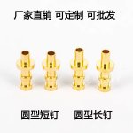
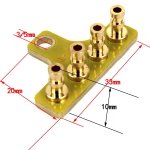
pillars/spacers/standoffs - just the different names of the same thing. Tell me the height of your pillars, of their hexagon part.
I can buy m3 copper pillars with lengths ranging from 3mm to 60mm. They are very cheap. I will buy copper pillars of several length specifications and try to assemble them directly, so you only need to tell me the possible suitable copper pillar length range.

I think the more problematic is the length of the pin header, because the maximum length of the pin header I can buy is 23.3mm.
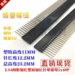
If there is a problem, I will remove the pin header soldered on the buffalo and replace it with a longer one.

I think the more problematic is the length of the pin header, because the maximum length of the pin header I can buy is 23.3mm.

If there is a problem, I will remove the pin header soldered on the buffalo and replace it with a longer one.
Last edited:
I can buy m3 copper pillars with lengths ranging from 3mm to 60mm. They are very cheap. I will buy copper pillars of several length specifications and try to assemble them directly, so you only need to tell me the possible suitable copper pillar length range.
I just trying to know what are the lengths of existing pillars you using right now to understand is there a need to replace existing to another ones. That is why I am simply asking you to measure your existing pillars with calipers. Because I think all other Buffalo users uses the same or very similar length pillars at least between the boards.
Pins of my transformer will be raised out from the PCB for ~6-7mm, that is why I just trying to understand do the other users needs to change (to extend) pillars between the boards or just the bottom pillars.
I think the more problematic is the length of the pin header, because the maximum length of the pin header I can buy is 23.3mm.
If there is a problem, I will remove the pin header soldered on the buffalo and replace it with a longer one.
Vice versa, there should be probably no need to use another length pins, that is why... Measure the pillars length please 😀
Regarding my board:
The bottom pillars between PCB and chassis should be not less than 25mm (hexagon part). Pillars between the boards should be 8mm (hexagon part again).
- Home
- Vendor's Bazaar
- Output transformers for DACs
