Pretty similar to this:
View attachment 801399
Dear bro ,
May I know price tag of transformer for 9038 pro Dac and pcb board ?idea for use quanho dac .
Best
$170 for transformersMay I know price tag of transformer for 9038 pro Dac and pcb board ?
$5 for PCB (without components, BOM available)
Last edited:
Beautiful pieces of art these trafos, thank you so much bisesik (Ivan) for making it possible. I am truly thankful for helping me out and providing a pair of trafos for my DSC dac.
The PCBs are actually a great idea with the detachable connection, so I can unplug the trafos if needed. Let's see if I have some spare time during the holidays to test them properly.
Some pics for everybody to see:


I wish you all great holidays and Merry Christmas, and thank you again Ivan for your great work.
Cheers
Pepe
The PCBs are actually a great idea with the detachable connection, so I can unplug the trafos if needed. Let's see if I have some spare time during the holidays to test them properly.
Some pics for everybody to see:


I wish you all great holidays and Merry Christmas, and thank you again Ivan for your great work.
Cheers
Pepe
I am now ready to try a pair of your transformers on the output of a AK4490/AK4493 DAC .Hi bisesik,
Your transformers look good.
I tested a Jensen JT-11-DM with a DAC AK4490 and it works really well.
If your transformers work as well then it's wonderful because the price is more interesting!
I'm going into active tri-amplification and I'll be interested in getting you a pair.
What is the delivery time and price for France?
Is it possible to have a picture of the inside of the box?
nounouchet
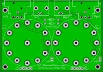
What is the size of the pcb supporting a transformer ?
What is the connection diagram with the new 13-pin format ?
The input impedance of the connected amplifier is 50-75K ohms. What resistance value do you recommend in parallel with secondary ?
Thanks.
Nounouchet
Thank you Pepe! I hope the transformers come in handy for celebrate Christmas well 🙂
Thanks.
Ivan
100x71mmWhat is the size of the pcb supporting a transformer?
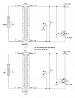
Simple: one primary to +/- of output, one secondary to RCA\XLR with one resistor in parallell (jumper for grounding RCA to avoid "humm" presented)What is the connection diagram with the new 13-pin format?
The same like without transformer as it will be 1:1.The input impedance of the connected amplifier is 50-75K ohms. What resistance value do you recommend in parallel with secondary ?
Thanks.
Ivan
...
Simple: one primary to +/- of output, one secondary to RCA\XLR with one resistor in parallell (jumper for grounding RCA to avoid "humm" presented)...
What is the meaning exactly with "with one resistor in parallel"?
Parallel of the output?
Yes, across the secondary coil - to stabilize the output impedance for all the frequency range. Kind of i/v resistor in common terms.
I thought, that the R across of secondary was for i/v purpose only.
From, what I have seen with the 1:1 yours transfo that I have, there is no any reason to apply a resistor (zobel in reality, R+C) across of secondary, the FR response is impressive flat at 10K, 20K, 100K next stage input.
From, what I have seen with the 1:1 yours transfo that I have, there is no any reason to apply a resistor (zobel in reality, R+C) across of secondary, the FR response is impressive flat at 10K, 20K, 100K next stage input.
Yes, you are right. With 1:1 there is no reason to use of resistor across the secondary.
p.s. For DSC DAC I recommend to use the step-up transformers (current-type, with resistor across the secondary as i/v). I thought about this kind of transformers when have been answering to nounouchet question, sorry. So, if it is 1:1 then just not use resistors at all 🙂
p.s. For DSC DAC I recommend to use the step-up transformers (current-type, with resistor across the secondary as i/v). I thought about this kind of transformers when have been answering to nounouchet question, sorry. So, if it is 1:1 then just not use resistors at all 🙂
Bisesik, Lemon,
Thank you for your answers.
It's clear form me with the schematic.
With Jensen transformer a use 600 ohm resistor accross the secondary, hence my question.
nounouchet
Thank you for your answers.
It's clear form me with the schematic.
With Jensen transformer a use 600 ohm resistor accross the secondary, hence my question.
nounouchet
The transformer manufacturer on datasheet, describes if there is need a secondary parallel resistor for better flat FR.
The best will achieved with a FFT that you can try different next stage input resistance and make yours experiments.
A Lundahl LL1545A needs a secondary zobel network to flatting the FR, the 1:1 bisesik not.
The best will achieved with a FFT that you can try different next stage input resistance and make yours experiments.
A Lundahl LL1545A needs a secondary zobel network to flatting the FR, the 1:1 bisesik not.
I have a question on my transformer (1:2+2) and the original ian adapter board.
so it looks like the board and transformer layout support either two 2+2 secondaries or one 4 secondary.
If primary is on bottom, the 4 secondary is on top, and the 2+2 secondaries are on the sides.
The rework instructions I'm looking at look correct if you have one 4 secondary, but incorrect for j3 if you have 2+2 secondaries.
I think you should cut the trace to the secondary closest to j3, and jumper from the pad you just isolated to bottom pin of j3.
Does that make sense?
Randy
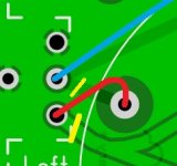
If it is about wrong XLR polarity, then yes, in case of 2+2 version it should be like you described:

Sorry Randy, I forgot that there was 1:2+2 version for you.
P.S. For all other users: if you do not know about this issue (via PM), then just ignore it, because this wrong XLR polarity connection was corrected in the next PCB revision..

Sorry Randy, I forgot that there was 1:2+2 version for you.
P.S. For all other users: if you do not know about this issue (via PM), then just ignore it, because this wrong XLR polarity connection was corrected in the next PCB revision..
If it is about wrong XLR polarity, then yes, in case of 2+2 version it should be like you described:
View attachment 804043
Sorry Randy, I forgot that there was 1:2+2 version for you.
P.S. For all other users: if you do not know about this issue (via PM), then just ignore it, because this wrong XLR polarity connection was corrected in the next PCB revision..
Thanks for confirming. I actually added one other jumper to make both sides the same, but since I guess I'm the only one with a 2+2 and first board no one else will care.
BTW, I have been using RCA's, and didn't realize I was missing two jumpers until this morning. I added those too, but a couple of the holes are messed up so I had to jumper them too.
Yes, across the secondary coil - to stabilize the output impedance for all the frequency range. Kind of i/v resistor in common terms.
Maybe the use of ONLY one output in same time is allowed. Other XLR or RCA should not been even connected with a cable. Because IF booth outputs are plugged in Rinput from next device will take a part in output circuit? As well as capacitance of cables... About 100pF typically probably more with connectors. In reverse step transfer that capacitance will transfer directly to the primary to the DAC outputs?
...
I want to say that in this configuration og secondary, only one cable should be used. XLR or RCA. Other unused output should be disconnected from any cable.
...
Worst case is that booth cables are connected from output of the transformer to inputs on preamps to choose with selector which one to use...
It is not specific for the these transformers but for any other used in this way.
.
Another thing, If I may, the core is probably without gap. So like it said there is any even slight offset DC difference at the primary taps is not good.
It that way, when we turn on DAC device, some imbalances in the circuit almost always causing DC offset at the output But in very short time until the circuit stabilized. Even these short "bursts" of delta offset at the output of dac and input to primary, can affect the sensitive high permeability, gapless transformer.
.
From my experience that could be avoided in dac power supply unit. Just make the supply have slow reaching level on power ON. About second or 2. Almost with every regulator it can be done. And in some regulators data-sheets we have examples how to.
.
That approach is also good to get rid of clicks and pops, avoiding mute relays and muting circuits, when turning ON device 🙂
.
Another thing, If I may, the core is probably without gap. So like it said there is any even slight offset DC difference at the primary taps is not good.
It that way, when we turn on DAC device, some imbalances in the circuit almost always causing DC offset at the output But in very short time until the circuit stabilized. Even these short "bursts" of delta offset at the output of dac and input to primary, can affect the sensitive high permeability, gapless transformer.
.
From my experience that could be avoided in dac power supply unit. Just make the supply have slow reaching level on power ON. About second or 2. Almost with every regulator it can be done. And in some regulators data-sheets we have examples how to.
.
That approach is also good to get rid of clicks and pops, avoiding mute relays and muting circuits, when turning ON device 🙂
Last edited:
I agree and believe it is useful instuction for any audio equipment which can work simulataneously to both types of outputs, no matter if there are transformers or any other components are used before connectors....only one cable should be used. XLR or RCA. Other unused output should be disconnected from any cable.

Sorry that I am wtriting 3rd post...
But it is good to know that we have difference with current output DACs versus Voltage ouput dacs.
Current output DACs with Riv used Shifting Voltage phase to -180deg. Opposite phase.
Positive digital DATA input DAC - Dac output current at Riv - giving -180deg Voltage output.
So it is need to check this and make transfprmer shift phase back into right pase output 0deg
.
Volttage output DAC has outputs are already marked as in phase or/and in phase. So only shifting element is transformer. Also it is good to check with simple measurements just to be sure. If it is outphase switch the secondary taps?
.
It is easely can be spotted by measuring Step response (more clear). Step response IF the ouputs are correct phase always should be firs going into positive Y axis. If the step response going into negative Y the output is outphase, and signal with -180deg going into the system.
.
(With exeption of Single ended tube (or other device) pramps - all single ended Gain stages shifting the phase -180deg.)
Last edited:
- Home
- Vendor's Bazaar
- Output transformers for DACs

