@bisesik
Ivan does you trafo for DSC will also work with this new project ? 🙂
https://www.diyaudio.com/forums/digital-line-level/345385-star-pure-dsd-dac-signalyst.html#post5978206
I think the difference is on the front end. Quanghao/Andrea added the ct7302 to generate the dsd stream.
Or did I miss something?
I think the difference is on the front end. Quanghao/Andrea added the ct7302 to generate the dsd stream.
Or did I miss something?
Yes, that's what I see too. The only variation on the output seems to be the inclusion of a relay to enable single-ended or balanced output to be selectable.
Thank you bisesik !
I will pm you then. I was not hoping a price like the chineese ones, don’t worry
In fact, there are more expensive transformers on Taobao. It uses 0.06mm 5N OCC and a 12.5~24mm thick core.
Primary resistance: ~ 1340 Ohms
Primary Inductance: ~ 1100-1200 Henry
FR 10Hz ~ 100KHz -0.2DB.
2 coils with PCB and Shield: 71~242 USD
5N单晶铜OCC漆包线绕制的美国Jensen战神10K:10K音频变压器复刻版
It is Neutron Star 2 Reference ClockI recognise most of the components in the picture but not the board under the tower raspi + DAC + transformers
What is it?
I have just tried bisesik's 0.5+0.5:4 PELSHO transformers with a new AK4499
DAC I am developing.
The results were very impressive.
I achieved 2v rms out using a 1k8 resistor across the secondary winding.
The DAC is configured in the register's for dual mono & I use the dual primary windings
to mix each pair of outputs from the AK4499.
DAC I am developing.
The results were very impressive.
I achieved 2v rms out using a 1k8 resistor across the secondary winding.
The DAC is configured in the register's for dual mono & I use the dual primary windings
to mix each pair of outputs from the AK4499.
It is Neutron Star 2 Reference Clock
Wow !!!
In which way did you connected the clock to fifopi ? Can you post some photos?
Do - I normally just build finished units but I have been thinking about DIY/shortform kits
lately so I will give it some thought.
lately so I will give it some thought.
Do - I normally just build finished units but I have been thinking about DIY/shortform kits
lately so I will give it some thought.
That would be amazing!
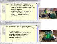
Here are comparative measurements with stock transformers. Nothing have changed during measurements - conditions are the same for both measurements.

Warning! This level of -10dB (0.62Vrms) was chosen due to highest SNR possible in my particular setup. I do not pretending for the best absolute measurings or exclusivity of my particular stand - it was just to compare transformers in the same conditions. Relation of THDs will be saved at any output level.

Warning! This level of -10dB (0.62Vrms) was chosen due to highest SNR possible in my particular setup. I do not pretending for the best absolute measurings or exclusivity of my particular stand - it was just to compare transformers in the same conditions. Relation of THDs will be saved at any output level.
Here are comparative measurements with stock transformers. Nothing have changed during measurements - conditions are the same for both measurements.
View attachment 796197
Warning! This level of -10dB (0.62Vrms) was chosen due to highest SNR possible in my particular setup. I do not pretending for the best absolute measurings or exclusivity of my particular stand - it was just to compare transformers in the same conditions. Relation of THDs will be saved at any output level.
Great! However, you are testing the Z11 transformer. You should buy clone Jensen's PT-11, use permalloy of the same material as biesik, for another testing. In addition, the transformer purchased from aliexpress is actually a counterfeit of "鷺歌", and there may be a drop in performance. It is recommended to buy it directly from 鷺歌 on Taobao.
美国Jensen战神 10K:10K音频变压器 终级复刻版鹭歌PT-11坡莫合金
SHOULD buy??? )))You should buy clone Jensen's PT-11...[/url]
It is simply false.use permalloy of the same material as biesik[/url]
Is somebody tested AK4499 in dual mono mode connected with transformer as on #291? Every coil between LxN and LxP (or RxN and RxP) mean in AsahiKASEI schematic IOUTLxN and IOUTLxP (IOUTRxN and IOUTRxP) I think. And where are connected OPINLxN/ OPINLxP (resp. OPINRxN/ OPINRxP) and VCOMLx (VCOMRx)? Thanks
SHOULD buy??? )))
It is simply false.
In order to explore the facts, I specifically asked the manufacturer. The manufacturer pointed out that the transformers they manufactured were old, because the test data recorded on the transformers were 422H and 430H, but the same transformer are currently between 1100H and 1600H. In addition, this transformer should have a shield, but you did not use a shield when testing, there is also unfairness in the test.
you SHOULD buy this transformer again for testing.
Last edited:
Sunyang, there was no such expirements AFAIK.
yunyun, can you ask the manufacturer regarding measuring of inductance at 1kHz instead of 100Hz? 😉
yunyun, can you ask the manufacturer regarding measuring of inductance at 1kHz instead of 100Hz? 😉
Last edited:
yunyun, can you ask the manufacturer regarding measuring of inductance at 1kHz instead of 100Hz? 😉
The point is that the object you are testing is their old transformer.
In addition, what is the significance of the inductance of the transformer? Using the same material to make the transformer, why are the inductances slightly different?
Sunyang, there was no such expirements AFAIK.
yunyun, can you ask the manufacturer regarding measuring of inductance at 1kHz instead of 100Hz? 😉
Chinese manufacturers said that they are used to measuring with 100MHz, so that they can measure different transformers with the same basis. They also said what you can also use 100MHz for measurement.

Last edited:
The point is that the object you are testing is their old transformer.
In addition, what is the significance of the inductance of the transformer? Using the same material to make the transformer, why are the inductances slightly different?
The real measured inductance (2-3 years after its manufacturing I think) of this EI (marked as 430H on photo) transformer is ~180H now at 100Hz. So the answer to your question pretty simple: difference in inductances are due to different plates permability within different transformers and due to wiring differences within one transformer (a bit less\more resistance), which are escalated over the time. To be honest the difference in pair of transformers even within 5-10% is a very good result as in the real transformer (not in theoretical, but in real) there is no inductive resistance only. Transformer is very complex thing and it is simply not possible to rely all the things needed for sound\music on inductances only, especcially at 100Hz only. But I believe the point is not that the object was old or new or in their absolute values of inductances. I believe mentioned transformers are still very good in terms of quality\cost. The more inductance you can get on the same dimmensions\wiring - the better perfomance - no questions. With hope that benefits (permability) will not go down over the time significally...
Chinese manufacturers said that they are used to measuring with 100MHz, so that they can measure different transformers with the same basis. They also said what you can also use 100MHz for measurement.
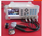
View attachment 796245
Sure they can measure at any frequency, but this particular measurement showned on photo (declared in specs) done at 100Hz.
The really interesting\sensitive things happens in another aspects of transformers. Seems that such regular (EI thick plate based) transformers simply stops to be transformers at higher frequencies if they have such a big amount of inductance\wire length, because the capacitive resistances between coils becames dominant over others. Transformer becomes... becomes... becomes capacitor 🙂
And if takes into account that 1:1 transformers are poorly suitable with current-type DACs (I believe DSC works better in current-output mode, similar to ES90x8 btw), and taking into account that step-up transformers works as LPF what is higly needed for DACs (Delta-sigma\SDM output especcially, remember Rasmussen filtering 🙂 ) - things becomes clearer a bit.
I know why this approach poorly works on other step-up transformers and clearly understand why people prefer 10k:10k over 600:10k of the same-type transformer, but it is another storry...
Clearer just "a bit" - because measurements very often are going in parallel or even in wrong direction when you comes closer and closer to the music in opposite to sound.
yunyun, I suggest to make the necessary comparative measurements from someone else, but AFTER real comparative listening within system that have no limit after DAC in terms of quality of following components. Reading your posts, I understand that I will always stays too interested person in this thread to to satisfy your curiosity 🙂
Thanks. TDA154x has DC-offset on the output, that is why one extra compensative (2mA) coil is used in addition to the primary coil.
Hi Bisesik,
Would you mind posting a diagram of how your trafo is connected with TDA 1514. I recall that the TDA had a 4ma of offset which needed to be null so wondering how your trafo design is set up for the TDA
Many thanks
Hi sumotan. Very good question! Yes, TDA1541 is very musical DAC, but it has some dificulties.
Previously I have used transformers with special DC-offset coil. But the price for such transformer looks a bit too costly compared to right-implemented regular transformer without special offset-coil. The difference between both approaches in THD measurements mainly was below 150Hz and was not very much (at least not 10 times less with offset coil as I remember - it was really not very hearable). And if taking into accout that DIYers mostly can not \ not want to make deal with additional complexity (extra PSU with needed voltage) during connectivity... I decided to provide simple one primary coil solution only (between Iout and gnd).
Anyway I think it is better to ask Dubai2000 about his experience with my transformers for TDA1541.
But time to time I am still wondering if it is possible to avoid dc-offset if to use 1541 in balanced mode (2x1541)?.. with simple connection of primary coil between Iout+ and Iout- with coil's CT at GND?.. But the demand for 1541 in our days is not high enough to allow me spend time for such experiments now, sorry 🙁...
- Home
- Vendor's Bazaar
- Output transformers for DACs