Using your carburetteurs as an analogy, the amp is tuned/balanced ike you tune the carbs. The ideal mix for econonomy, but not too lean.
The output tubes and the B+ that will be across them will dictate the 'richness' of the mixture. The OPT primary impedance is the load that the tubes see, and the 'idle' point is determined by the load line that is derived from the OPT impedance and the graph of tube current vs anode voltage for different grid voltage settings.
Within bounds, there is leeway to optimise for power, distortion and tube life.
The starting point is to define what you want to achieve from a pair of GU-50 tubes. What is their max dissipation? You have 400V supply. What anode-anode load suits them best (in the tube data). Then most of it is decided for you.
Seeing as how all the data sheets for the GU-50 Tube are either in Russian and only mention the loads for RF it's a bit difficult to tell.
The GU-50 Data sheet is not as easy for me to understand as some others.
I suppose that's the risk when using an RF Tube as an AF Amp Tube.
But I believe many people have done it successfully.
Im not looking to build a 70W or higher monster amp.
I would be happy to build a 35-40W amp that sounds good and looks impressive and can be turned up now and then.
I just really liked the idea of building an amp using all Russian sourced Tubes and I admit to liking the aluminium garbage can holders that are made for the GU-50.
I bought the cans and tubes (on a certain auction site)
Next thing I know the seller messages me that he is putting extra in the box for me because I am immediate payer and good Aussie bloke.
Just hope ASIO don't turn up on my doorstep when boxes of slightly radioactive aluminium cans and Russian RF tubes from the Rocket guidance systems of the cold war get delivered to my workplace.
Attachments
if you want lower output power, then you can use lower B+ and lower anode to anode loads for your opt..
Last edited:
If you have TME.EU in Fostersland then you may be able to get them delivered cheaply.
Took me a while to figure out what you were getting at there.
Seems to be a common misconception about Australians and Foster's Beer.
We don't drink it. Never seen it for sale in a pub. Never tasted it. Just like every other country, we export the crap we don't want and then drink the good stuff or foreign beers ourselves.
I remember their add campaign in the 80s was
"Ahhh Foster's. It's got the flavour, that's taken it all round the world"
That's a polite way of saying
"It tastes like toilet water so we sell it overseas instead"
Found this calculator in another thread that tells me I will get 56W output from PP GU-50 400V/150mA driven into 5K:8ohm
Universal loadline calculator for vacuum tubes - Vacuum Tube Amplifiers - DIY
Seems a decent number that I would be happy with.
Don't know how good the load calculation is though.
🙂
Castlemaine then!
There is a lot to be said for getting some boards for something like the Baby Huey EL34 (that will work with other power tubes), then starting with a known baseline, and taking advantage of the excellent support here, then adapting the solution to your tubes.
A lot of the investment would be recovered - the OPTs, case, hardware, etc.
Or one of those Chinese kits that use those tubes, and rebuilding it to the next level.
Or is it going to be for a musical instrument?
Hi Hector,
No I want to build a HiFi amp based on the Mullard 5-20 design using all Russian tubes.
Somehow it seems I have also purchased 32 x 6P14P which is the Russian equivalent of the EL34 for $2 each.
Damned finger print and facial recognition on my phone did the transaction on its own after I accidentally bumped accept offer.
Anyway...
6Ж32П (EF86) For input tubes
6N2P (ECC83) Phase Spliter
GU-50 as PP Output Amplifier tubes. I heard these tubes described as EL34 on steroids.
I think I found the output transformers at Evatco at a reasonable price but I have to double check the stat's on them first. Not going to buy the expensive bits yet till I know more.
I am thinking I will need a bigger power transformer to make a stereo unit.
I only have a single second hand unit at the moment as follows.
240V Primary
400 - 0 - 400 @ 150mA
5 - 0 @ 3A
6.3 - 0 @ 4A
2.5 - 0 @ 3A
If I could find a cheap amp here in Straya as the bare bones and start from that I would. But Strayans seem to want top dollar for everything and importing from UK or USA ends up being more in postage than the sum of the parts.
I nearly bought one of those cheap Chinese kits but in the small print it seemed nothing was included except the full technical notes on what parts to buy.
Would have been about $300 for some circuit boards and a bag of cheap Chinese caps and resistors. And even cheaper looking plastic tube sockets.
I really need to wear my glasses when looking at ebay on my phone. Seems I bought some GU-19-1 Tubes 2 days ago and already paid for them. I have NO idea why or what for.
They can go on the shelf with the E15 I bought by accident a few years back which is wrapped in Asbestos wool and somehow made it through the post.
Think I better turn off some of my automated passwords on my phone for PayPal and the likes.
Did I mention that I used a pair of small, conventional power transformers, in reverse, for a headphone amplifier with a single 6360 dual tetrode. (I started using the 6360 50+ years ago in VHF transmitters)
Output Transformers are the one thing that really confuses me and dealing with loads etc.
I have only ever worked with very basic PA systems where the output TFR was mounted in the speaker housing to convert a 100 volt line to a really crappy audio signal for shop music and announcements.
When I was a kid we did horrible things at the local pool like hook a wire from the 100V line to the door handle of the dressing room which worked great because the floor was always wet and the door handle was an old style brass knob.
Figuring out load impedance of vacuum tubes is a little harder to grasp than electrocuting your friends for fun.
Im worried now I don't understand Power transformers as well as I thought either.
f I have an input transformer that has a 1000V/170mA winding with a centre tap. Does that mean I can do 2 x 500V supplies to a stereo amp and feed them each a rectified 500V/85mA into the CT of the OPT? Am I correct in assuming the mA drops with the voltage?
Pictures of exact transformer attached for clarification
Attachments
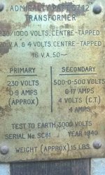
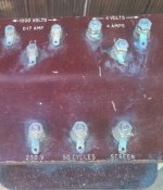
No you can only simply generate a single B+ dc output with a V-0-V secondary winding.
The 170mA rating relates to the AC rms current of the winding. You can estimate the winding rms current required for a given dc load on the generated B+ voltage and rectifier/filter using the software PSUD2. It would be well worth your while to read all the help notes etc for that program as a learning curve.
The 4Vac 4A heater winding and early date of 1940 indicates it was used with early audio valves like the MHL4 and PX4, but there only appears to be one 4V winding so that is a concern as that wouldn't allow a rectifier tube like a MU14 - but heh, it's not 1940 🙂
Thanks TRobins,
Now I am confused then. So what is the point of the 2 x 500V & CT?
If you don't use the CT do you get 1000V?
Unfortunately that program PSUD2 requires an operating system that can not be named.
No not Voldemort... Windows.
Every PC in my house (and there is quite a few) runs Linux Mint or Ubuntu.
I abandoned MS years ago.
Loading it on the work laptop isn't an option either due to lack of Admin rights on the machines. For some reason they don't trust us 😀
PSUD2 runs under wine. It is so easy to mix and match different variants of power supply with PSUD2, and get confidence in what you are building. It is essential if you are winging it with your own design.
Maybe Bill Gates is getting the last laugh here?
Maybe Bill Gates is getting the last laugh here?
PSUD3 is aiming to have a Linux install - but unsure of progress on that.
The 500-0-500 would have been aimed at choke input filter along with a vacuum tube rectifier (which needs the V-0-V format as they can't easily be used to full-wave rectifier a single V winding). The voltage drop of the rectifier, and the choke input, would have generated something like a 400Vdc B+ supply.
But nowadays it is not common to use a 500-0-500V secondary, as it generates a relatively high DCV (with ss diodes and capacitor input) that is beyond what most output stage tubes can handle, and is best used for high power amps that are likely too high in power for most.
Last edited:
I think your right. Bill Gates is certainly laughing at me thats for sure.
I cant install WINE for some unknown reason and have not been able to correct the issue with help from the forums either.
Same error always comes up
The following packages have unmet dependencies:
winehq-stable : Depends: wine-stable (= 6.0.1~focal-1)
E: Unable to correct problems, you have held broken packages.
But this is not the forum for that.
Might just have to locate my old HDD with Win XP on it and boot into that on one of my machines.
Then wait 62 hours for it to perform all the updates which is why I hate Windows so much.
The point of the 2X CT winding is to use a two diode full wave, using the center tap to ground. You can get a full wave rectifier with a single dual-diode valve and only one heater winding. If silicon diodes are available, you can think outside of that box. But in 1940 no one did.
If you don’t use the CT you get 1000. You could get 500 and 1000 by connecting to the CT for the 500 volt tap with a full wave (4 diode bridge), and there are cases when such would be useful. But not for your typical beginner project. A SET using transmitting triodes, with the front end running off lower voltage, for instance. Shocking, for sure. Dangerous voltage, and the tubes and required high Z output trafos would send you into sticker shock. And output power is still limited by the power trafo.
If you don’t use the CT you get 1000. You could get 500 and 1000 by connecting to the CT for the 500 volt tap with a full wave (4 diode bridge), and there are cases when such would be useful. But not for your typical beginner project. A SET using transmitting triodes, with the front end running off lower voltage, for instance. Shocking, for sure. Dangerous voltage, and the tubes and required high Z output trafos would send you into sticker shock. And output power is still limited by the power trafo.
All Generalizations Have Exceptions.
Generalizations:
Two B+ power supplies, that have the same output voltage, and the same output current:
A 0-500V secondary and a 4 diode bridge gives about 707V at the cap input filter.
A 500-0-500V secondary and 2 diodes gives about 707V at the cap input filter.
There are more wire turns in the 500-0-500 secondary, versus the 0-500V secondary.
To get the same DC load current, the cross section Area of the 0-500 secondary needs to be 2X the cross section Area of the 500-0-500 secondary.
The tradeoffs are:
More turns and 4 diodes
More cross section Area, and 2 diodes.
Of course, you coulf use the same wire cross section Area, but the 0-500V will either run hotter, or maybe catch fire.
707 volts for a cap input filter with no load, and 450 volts (minus Rdc*Idc) for a choke input filter at full load. With reality being somewhere between the two - which is why you need PSUD and load test measurements.
500-0-500 is 1000vac ct....into a full wave bridge, you can get 1400vdc and 700vdc at the center tap, assuming that was a capacitor input psu...these are peak dc values of unloaded voltages...
final voltage(aka loaded voltage) of course depended on your equivalent load resistance in series with your traffo secondary dc resistance referenced to primary...
R = [(vpri/vsec)^2 x sec rdc]+ sec rdc secondary
these are all ohms law calculations btw, of course would be nice to see those startups at PSU II...
you can draw the Thevenin equivalent circuit for analysis...
Last edited:
Who knew that to build a Tube Amp I would first need to rebuild a Windows Laptop to run the PSUD2 software.
This poor old HP has been running great on Linux Mint and seems to have gone into shock at receiving its original HDD back. Waited 136 minutes for Windows to load and try to run updates and now learning how to use PSUD2.
Thanks for the suggestion guys. Will report back once I have learnt something and have some kind of result.
Attachments
- Home
- Amplifiers
- Tubes / Valves
- Output transformers a cheap alternative?