I get the secondary wiring, but the primary wiring confuses me.
SEC 1 and SEC 2 are in parallel. Easy enough.
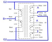
PRI 1 and PRI 2 are in series-parallel(??).
So for the VPT12-8330, the drawing shows it wired 115V-0-115V:12V, correct?
--
SEC 1 and SEC 2 are in parallel. Easy enough.
PRI 1 and PRI 2 are in series-parallel(??).
So for the VPT12-8330, the drawing shows it wired 115V-0-115V:12V, correct?
--
Secondaries are actually in series.
Primary is set up the DC flow cancels in the cores.
It actually shows effectively 230 - 0 - 230 : 24 where each 230 is made from one half of each coil and the 24 is made of two 12s in series.
Primary is set up the DC flow cancels in the cores.
It actually shows effectively 230 - 0 - 230 : 24 where each 230 is made from one half of each coil and the 24 is made of two 12s in series.
Wow. My bad. Bad brain.
OK, the secondary. Follow the electrons from - to +.
SPKR NEG > SEC 2-1 dot > no dot > SEC 2-2 dot > no dot > SEC 1-1 dot > no dot > SEC 1-2 dot > no dot > SPKR POS.
Now my brain hurts. But I think I got it. Thanks.
If this was a pair of VPT12-xxxx (230V:12V) xfmrs, how do you figure what primary impedance is being reflected from a 6 ohm load across the secondaries?
--
Does that end up with lower secondary dc resistance than picking a different ratio transformer that allows you to put the secondaries in parallel?
Probably not but we're talking milliohms... Every VPT12 or VPT18 secondary I've metered come in at 0.1R.
You could use VPT24 in series parallel, or VPT48 in parallel parallel. and still get 2k2:6R but the 12 and 18 parts are more common.
You could use VPT24 in series parallel, or VPT48 in parallel parallel. and still get 2k2:6R but the 12 and 18 parts are more common.
OK....
HELP?!!!!
Can you describe the connections required to connect the secondaries of two 'interleaved' VPT18 transformers in parallel, to make 2.6k:4 ohms?
I tried to puzzle it out, and I failed.
--
HELP?!!!!
Can you describe the connections required to connect the secondaries of two 'interleaved' VPT18 transformers in parallel, to make 2.6k:4 ohms?
I tried to puzzle it out, and I failed.
--
Here is another possibility, which has the added benefit of possible UL operation. By using 4 different high voltage windings it may have enough inductance in a single OPT.
This is Antek AS-1T150 but there are several others with different high voltage secondaries so you can get a range of impedance ratios.
Has anybody tried this?
This is Antek AS-1T150 but there are several others with different high voltage secondaries so you can get a range of impedance ratios.
Has anybody tried this?
Attachments
Hi, may I ask you if my calculations are correct?
An old project I had was a bass amp with a sextet of GU-50 capable of around 350Wrms.
Let's consider 850V B+ and 10k Raa for each PP, so 3k3 total for a 4 Ohm cab.
This means 825:1 Z ratio, so 28,7:1 V ratio, so 230-0-230V to 16V.
Two Hammonds 1182S15 (https://www.mouser.it/datasheet/2/177/1182-736858.pdf) with 2x115V primaries in series and 2x15V secondaries in parallel would give around 3k7.
It would be expensive, but way less than a custom OPT for the purpose.
Will it be ok with a B+ of 850V?
Thanks for the confirmation.
These transformers are not rated for a sustained 850V supply. They will likely fail catastrophically if abused in this way. Don't do it.
Shoog
Shoog
The only off the shelf transformer that I’ve found that could potentially be “abused” that way at that much B+ is the Antek 15T950. Using the 120v primary for the speaker. 1k a-a at 4 ohms, 2k at 8 ohms. Since it is designed to be nominally 1900 VCT it should be able to take that kind of voltage. It looks like it’s physical construction is two independent bifilar would 2x475V windings, according to the hookup diagram printed on it. Since it is hard wired to give two CT windings, it is not possible to interleave the two sets of windings - nor would that even be advised at these voltages if you could. It would give 50% UL taps, if you could make use of it. I doubt some crazy transmitting tube would work well in UL, and for sweeps it’s out of the question. A big bank of KT88’s maybe.
The 8T800 could be used similarly, but at much lower B+. The Ra-a is even lower, and ultimately the *current rating* of the winding will limit your max power and useable B+. And no UL taps. It could do 350 watts, at maybe 500 volts tops. For use with sweep tubes operating at high peak Ik and low B+ it’s a possibility.
The 8T800 could be used similarly, but at much lower B+. The Ra-a is even lower, and ultimately the *current rating* of the winding will limit your max power and useable B+. And no UL taps. It could do 350 watts, at maybe 500 volts tops. For use with sweep tubes operating at high peak Ik and low B+ it’s a possibility.
Thank you guys!
OT with this section of the forum: can this trick be applied to have cheap output transformers for guitar amplification (they usually are secondary-primary-secondary or secondary-primary-secondary-primary-secondary) around 500V B+?
OT with this section of the forum: can this trick be applied to have cheap output transformers for guitar amplification (they usually are secondary-primary-secondary or secondary-primary-secondary-primary-secondary) around 500V B+?
Hi all,
I just read this whole thread and didnt find the answer I was looking for.
How do you know or measure what size output transformer you need?
I am trying to teach myself more and more about Tube amplification and there seems to be some gaps I cant fill.
I swear I just watched about 3 videos & read multiple posts of people who all built what seemed to be the same amplifier but all used different output transformers and claimed different output wattage.
All the circuits seemed to be a Mullard 5-20 using GU-50 as output tubes.
the output transformers ranged from 2.5K to 8K / 8ohm with claimed outputes from 25W to 70W
How can so many people be building the same circuit and getting such different results?
Does the output transformer have that much effect on the final output of the amplifier?
And how do you measure what the K ohms is between the 2 output tubes to get the correct transformer?
HighVoltageHit,
In order to determine what output transformer you need, you must first decide:
What output tube(s) you will use
Push Pull:
Class A, Class A2
Class AB, Class AB2
Class B, Class B2
For Pentode and Beam Power tubes, will you use Ultra Linear mode, Triode Wired mode, or the Pentode and Beam Power modes.
Will you use Triode tubes.
Will you use Cathode negative feedback.
Will you use Global negative feedback.
What frequency range must you have, low to high frequency.
What output impedance tap(s) do you want.
What output tube(s) you will use
Single Ended; Parallel Single Ended:
Class A, Class A2
For Pentode and Beam Power tubes, will you use Ultra Linear mode, Triode Wired mode, or the Pentode and Beam Power modes.
Will you use Triode tubes.
Will you use Cathode negative feedback.
Will you use Global negative feedback.
What frequency range must you have, low to high frequency.
What output impedance tap(s) do you want.
Picking the right output transformer is quite complex.
But consider this:
You are designing a car, it will have an 8 cylinder engine, and a 4 speed transmission.
How will you pick the right transmission, if . . .
One racing 8 cylinder engine revs to 12,000 rpm, has low torque, and 400 Horsepower.
One touring 8 cylinder engine revs to 6,000 rpm, has 400 pounds torque, and 400 Horsepower.
Now consider a pair of output tubes in push pull, that either runs at 500V and 50mA per tube, or the same tubes that runs at 300V and 83mA each.
The plate dissipation in each case is 25 Watts.
But the output transformer required is completely different for those two operating conditions.
Last edited:
Is the mA output of the tubes determined by the power input of the main power transformer?
Say for example a Mullard 5 pp design using 2 x GU-50 output tubes and a mains supply of 400V 150mA.
Does this then mean each tube is putting out 75mA at the end?
Say for example a Mullard 5 pp design using 2 x GU-50 output tubes and a mains supply of 400V 150mA.
Does this then mean each tube is putting out 75mA at the end?
remember that with tubes, we are dealing with peak and peak to peak values of voltages and currents....with sine waves it is easy to figure out rms values, but with music?
Hi Tony,
Even more terminology and factors I have to wrap my head around.
But it makes sense that if the original supply was 400V 150mA then rectified voltage will be a little higher but the 150mA isn't going to change or disappear so the OPT needs to be able to handle the peak or be slightly oversized in case of spikes etc.
Transformer ratings are complex.
Just because a transformer is rated at 150mA, does not always mean that you can get 150mA DC out of it into solid state diode rectifiers driving a large capacitor input filter.
That transformer is likely going to be very hot if it is used that way.
Often, the 150mA rating is into a resistive load.
I do not know the link, but several threads give the link to the Hammond power transformer document.
It shows how all those ratings work, and how they change versus the kind of rectification,
full wave with center tap, bridge rectified, 1/2 wave rectifier, cap input filters, choke input filters, and resistive loads (no filter).
Think of the power transformer as the motor.
Think of the output tube as the gas pedal and carburetor/fuel injector.
Think of the output transformer as the 4 speed transmission.
Power, Control, and matching ratio.
Last edited:
Geez I wish it was that easy.
I can rebuild and tune a Stromberg or Webber Carbi in my sleep.
Another unused skill I acquired from my life of buying $300 cars in the 90's
I can rebuild and tune a Stromberg or Webber Carbi in my sleep.
Another unused skill I acquired from my life of buying $300 cars in the 90's
- Home
- Amplifiers
- Tubes / Valves
- Output transformers a cheap alternative?