I have been using 6SN7 Mu follower and CF and I would like to order a custom-built output transformer for the preamp. Can anyone help me with the transformer spec for that? Many say the detailing and SQ are very good with output transformers.
I would like to know what is the primary and secondary resistance.
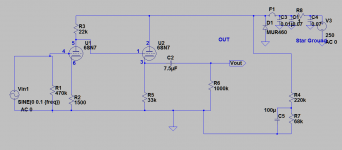
Primary and secondary inductance spec if required. The sch is as attached.
I would like to know what is the primary and secondary resistance.
Primary and secondary inductance spec if required. The sch is as attached.
Attachments
what should be the primary and secondary resistances? I see audionote has about 35:1 ratio so if we consider 10k as primary so secondary needs to be at 285ohms?
Wasting Our Time Again
'rhythmsandy' will continues to waste our time.
Check the record in the bio, averages one post per day.
Has anyone ever seen a completed project?
And where is the mu follower in that schematic??🙄
Recently 'rhythmsandy' spent 10 months discussing this circuit but with no results either in hardware or data. Much talk, no action!!
True its impedance. Yes secondary needs to match to the load or in case of pre it has to be atleast 10x lower than the amplifier input impedance. Agreed but to order for a custom designed transformer the spec has to be clear and Im planning to get it done in amorphous core so need a details spec if possible.The secondary impedance is designed to match the load.
Resistance is not impedance!
Stewart the pre is working properly as I have mentioned in other thread. The problem was heater and my input pin being 1 it had issues with hum and now its solved. Thanking you very much. Just wanted to try using output transformers instead of capacitors so rather spending money on Duelund we can get transformer done for it. So just wanted to check with you guys if anyone has custom ordered an output transformer which you might have faced problems with particular ratios.'rhythmsandy' will continues to waste our time.
Check the record in the bio, averages one post per day.
Has anyone ever seen a completed project?
And where is the mu follower in that schematic??🙄
Recently 'rhythmsandy' spent 10 months discussing this circuit but with no results either in hardware or data. Much talk, no action!!
Stewart the pre is working properly as I have mentioned in other thread. The problem was heater and my input pin being 1 it had issues with hum and now its solved. Thanking you very much. Just wanted to try using output transformers instead of capacitors so rather spending money on Duelund we can get transformer done for it. So just wanted to check with you guys if anyone has custom ordered an output transformer which you might have faced problems with particular ratios.
Shew us a finished project.😀Just one.
Here are some of the pics
Dropbox - whf_amp.jpg - Simplify your life
Dropbox - 50W class A monoblcok.jpg - Simplify your life
Dropbox - whf_amp.jpg - Simplify your life
Dropbox - 50W class A monoblcok.jpg - Simplify your life
NO Mu follower in that schematic.I have been using 6SN7 Mu follower and CF
This is starting bad.
That preamp as shown does not need an output transformer. 🙄and I would like to order a custom-built output transformer for the preamp. Can anyone help me with the transformer spec for that?
Maybe, IF needed.Many say the detailing and SQ are very good with output transformers.
But you are just blindly repeating something you read somewhere, with no clue and completely out of context.
Resistance is not impedance.I would like to know what is the primary and secondary resistance.
Hardly a transformer needed there and you omit the most important data: what is your load?Primary and secondary inductance spec if required. The sch is as attached.
Unless your question is not technological buy mystical: "transformers have such and such magical properties and I want them in my design, just by randomly adding one"
In that case, you may simply mount o e in your chassis, without even connecting it to anything.
Hey, what you did with that unneeded MUR460 diode.
maybe you read "they improve xxxxx" (xxxxx being some desirable quality) and so HAD to add one.
Design does not work that way, but a real Technical need has to be solved, and components are calculated and chosen for that. Not randomly placed because of some intrinsic quality they may impart to sourrounding components by their mere presence.
Also the "connected to nothing" voltage divider and smoothing capacitor R4-R7-C5 😕
Not too sure either about the "do nothing" RCRC filter C1-C3-C4-R8 😕
1 ohm resistor? .01 and .07 capacitors? Besides the nil effect on filtering, what do you expect them to accomplish?
And the hardly useful F1 fuse on the +V line?
Not even shorted tubes will blow any currently available fuse.
"Design" looks like randomly copypasted schematic snippets from different places.
well that psu part ive been just using a a conventional template and 1ohm is to probe current while measuring.
The resistor network R4 , R7, C5 is for heater elevation.
The amplifier input impedance to which I will be connecting the output transformer will be in the order from 20k to 100k any of them.
The reason why im considering the transformer is ofcourse said by some audiophiles and also some companies like audionote uses them in their preamps.
I agree the part that using just a transformer doesnt make sense but I have used input transformers earlier and the sound was way too good hence thought why not use a trafo for the output of the preamp output hence thought to consider after reading the articles on audionote for example. Even jacmusic uses transformer for the eml lab 20b v4 tube.
Nice pictures, where did you copypaste them from?
Complex builds not exactly compatible with experience and Tech levels you show in your questions.
Meaning, "we all started from 0", so nothing against that, but I find it hard to imagine a continuous path connecting the schematic shown above and the gorgeous build depicted.
I mean the Class A amplifier; the fuzzy black box shown in the other picture may be anything ... even an empty case sitting on a table.
Hardly a transformer needed there and you omit the most important data: what is your load?
Perhaps it is needed to isolate ground loops.
Nice pictures, where did you copypaste them from?
Complex builds not exactly compatible with experience and Tech levels you show in your questions.
Meaning, "we all started from 0", so nothing against that, but I find it hard to imagine a continuous path connecting the schematic shown above and the gorgeous build depicted.
I mean the Class A amplifier; the fuzzy black box shown in the other picture may be anything ... even an empty case sitting on a table.
wait wait let me show you my other build
Dropbox - 2019-09-11 15.06.07.jpg - Simplify your life
Dropbox - 2019-09-11 15.05.54.jpg - Simplify your life
power rating of 2 channel is 700W RMS into 4ohms with 2,00,000uF psu capacitors, 100Amp bridge rectifiers. 5 pairs of MJL21193/94 driven in triple EF with Class A driver stage.
I'm just very new to tubes and hence have many questions regarding that and didn't seem as much straight forward as solid-state.
rhythmsandy … the secondary pictures further support Fahey's contention, you know. While those are some solid specifications, in the end, your 6SN7 'preamp' with cathode-follower schematic has a lot of mmm… pointless… things going on.
Template-or-not, its kind of like taking pictures of a well-decorated wedding cake, and then asking questions about how much sugar to add to the eggs before making the batter.
As we say in America, “the curtains don't match the carpet”.
⋅-⋅-⋅ Just saying, ⋅-⋅-⋅
⋅-=≡ GoatGuy ✓ ≡=-⋅
Template-or-not, its kind of like taking pictures of a well-decorated wedding cake, and then asking questions about how much sugar to add to the eggs before making the batter.
As we say in America, “the curtains don't match the carpet”.
⋅-⋅-⋅ Just saying, ⋅-⋅-⋅
⋅-=≡ GoatGuy ✓ ≡=-⋅
Last edited:
Bunk!!🙄🙄🙄
Like said regarding the tubes I'm very new to valves and also the transformers are quite expensive so just asking a few of you to check that am I choosing the right component or not.
PS - but thank you for admitting you are new-to-tubes, and they're confusing. Yes, they are.
Take the advice now already given: you do not need an output transformer on a preamp. Period. Instead, concentrate on the values your little diagram has, at various positions. Reduce and remove things not needed (such as the power supply leading to ground … with a blôody capacitor on that path (to the right)). Its pointless.
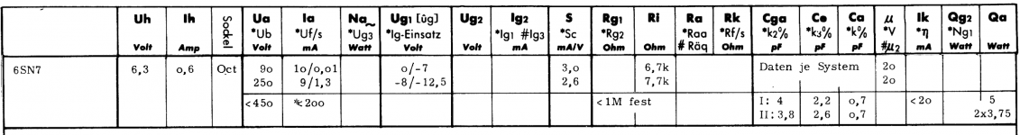
The circuit shown ought to have a 3.8 mA quiescent (no signal) current in 6SN7 (left). This induces a voltage of 5.7 V in the 1,500 Ω cathode 'auto-bias' resistor. Which corresponds on the 6SN7 load-line datasheet diagram to … just that. Yay. In turn, the 22 kΩ anode resistor will DROP 84 volts, leaving the valve to “see” 250 - 84 = 166 volts on anode. And 5.7 v on cathode. 160 V total, across.
Without a cathode bypass resistor, the 1,500 Ω cathode resistor will be exerting a strong local-negative-feedback moderation to the already-quite-linear 6SN7's triode transfer function. The result is that the signal tapped up on the anode resistor will be quite linear. This I presume is desired.
Moving along however, the next stage has a 33 kΩ cathode resistor and is seeing 165 V on the grid. 165 V ÷ 33,000 = 0.005 amp or 5 mA passing thru. Output impedance (perhaps unexpectedly to you as a newbie…) is rather markedly lower than 33 kΩ tho'. As Fahey (or someone) said above, around 10 kΩ.
And … 10 kΩ is a perfectly good output impedance for a preamplifier, especially driving what looks like “high end” audio equipment.
The 7.5 µF capacitor … is fairly misguided though. The formula
Anyway, more than you wanted, its likely.
⋅-=≡ GoatGuy ✓ ≡=-⋅
Take the advice now already given: you do not need an output transformer on a preamp. Period. Instead, concentrate on the values your little diagram has, at various positions. Reduce and remove things not needed (such as the power supply leading to ground … with a blôody capacitor on that path (to the right)). Its pointless.
The circuit shown ought to have a 3.8 mA quiescent (no signal) current in 6SN7 (left). This induces a voltage of 5.7 V in the 1,500 Ω cathode 'auto-bias' resistor. Which corresponds on the 6SN7 load-line datasheet diagram to … just that. Yay. In turn, the 22 kΩ anode resistor will DROP 84 volts, leaving the valve to “see” 250 - 84 = 166 volts on anode. And 5.7 v on cathode. 160 V total, across.
Without a cathode bypass resistor, the 1,500 Ω cathode resistor will be exerting a strong local-negative-feedback moderation to the already-quite-linear 6SN7's triode transfer function. The result is that the signal tapped up on the anode resistor will be quite linear. This I presume is desired.
Moving along however, the next stage has a 33 kΩ cathode resistor and is seeing 165 V on the grid. 165 V ÷ 33,000 = 0.005 amp or 5 mA passing thru. Output impedance (perhaps unexpectedly to you as a newbie…) is rather markedly lower than 33 kΩ tho'. As Fahey (or someone) said above, around 10 kΩ.
And … 10 kΩ is a perfectly good output impedance for a preamplifier, especially driving what looks like “high end” audio equipment.
The 7.5 µF capacitor … is fairly misguided though. The formula
C = 1,000,000 /(2 π F R) (in microfarads)
C = 159154 / ( 20 Hz × 10,000 Ω )
C = 0.8 µF
shows that the 7.5 µF is 10× bigger than need be. 2× or 3× bigger is a better choice. And, taking a look at the magic-unicorn-dust cut-and-paste power-supply capacitors, you really would want to have a 0.05 µF capacitor in parallel with a 2.0 µF electrolytic. HF response, so “they” say.C = 159154 / ( 20 Hz × 10,000 Ω )
C = 0.8 µF
Anyway, more than you wanted, its likely.
⋅-=≡ GoatGuy ✓ ≡=-⋅
jhstewart₉;6039505 said:Bunk!!:rolleyes∴rolleyes∴rolleyes:
LOL… I think “rhythm” is a builder (or buyer) of fine kit-ware. But let's give him a little break: for reasons unknown, he wants a preamplifier. OK, the 6SN7 is good, he still has to figure out what power supply schematic is really useful (i.e. get out of the circuit simulator!), and so on. Hopefully, if he takes the advice of others, it'll come to fruition.
Otherwise, we're just endeavoring to educate the fella. Which is OK too.
As always, appreciating your pithiness, JH.
⋅-=≡ GoatGuy ✓ ≡=-⋅
- Home
- Amplifiers
- Tubes / Valves
- output transformer spec for 6SN7 Cathode Follower