If I had to work with 6sn7 what value of inductance should be in primary to get a good LF response?I probably shouldn't butt in here; but here goes. I personally prefer the sound of transformer coupled output to capacitor coupled output. But to achieve this takes a really good line out transformer and they aren't cheap. It also requires designing the circuit for transformer output. It's not something that can be necessarily grafted onto some existing design.
Second, a 6SN7 has too high a plate impedance to drive a transformer effectively. That would require a very high primary inductance for decent bass response but that in turn would require more windings. That results in more winding capacitance which interacts with the plate resistance to kill the high frequency response. You're going to have to use a higher transconductance tube and more B+ current to bias that tube. So PS is going to have to be able to handle the extra load.
I'm currently in the process of building a headphone amp with a modified 6SN7 mu follower (Morgan Jones "beta follower") doing input/voltage gain duty. In Jones' circuit the load resistor is replaced by an PNP transistor. This has three advantages: 1) consumes less B+, 2) output of the lower tube is direct coupled to the upper - no capacitor and 3) the AC impedance of the upper tube is multiplied by the transconductance of the transistor ( hence beta follower). This presents the lower tube's plate with a much higher impedance load. The output is RC coupled to the following stage, a transformer loaded 6BX7. With a plate resistance of ~2.5K the rule of four would suggest a primary impedance of 10K. If interested I will let you know if it sounds any good when I'm finished.
Good luck with your project.
So it is not your design. You are employed to assemble the parts. I'm really impressed now. Just build something, stop talking about what you might do.
Talk is cheap.😀
I have contributed my part in design as well.
Example posted by OP claiming to be his own builds
Image from a Banglore India Hi Fi show:

The source of the other "example" hasn´t been found (yet).
Didn´t even open the images added as "additional proof"
Back to the original project:
* just build it
* no need for output transformer. (The amplifier input impedance to which I will be connecting the output transformer will be in the order from 20k to 100k any of them.)
* no, it won´t "improve sound" just by sitting there with no defined job to do.
* IF you use a 35:1 (impedance) transformer there you´ll also add a 6:1 attenuation to output signal, did you consider that?
An externally hosted image should be here but it was not working when we last tested it.
Image from a Banglore India Hi Fi show:
The source of the other "example" hasn´t been found (yet).
Didn´t even open the images added as "additional proof"
Back to the original project:
* just build it
* no need for output transformer. (The amplifier input impedance to which I will be connecting the output transformer will be in the order from 20k to 100k any of them.)
* no, it won´t "improve sound" just by sitting there with no defined job to do.
* IF you use a 35:1 (impedance) transformer there you´ll also add a 6:1 attenuation to output signal, did you consider that?
Both sections of a 6SN7 in parallel cut the OPT inductance requirements in half. Subing in a 6BL7 would further reduce the inductance further.🙂
The preamp could be isolated from the main amp by cutting the connexion between the preamp common & the main amp common, thus avoiding a ground loop.Done all the time in broadcast work.
The preamp could be isolated from the main amp by cutting the connexion between the preamp common & the main amp common, thus avoiding a ground loop.Done all the time in broadcast work.
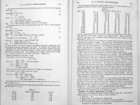
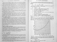
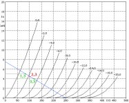
Here, have a read.If I had to work with 6sn7 what value of inductance should be in primary to get a good LF response?
Attachments
-
 prim-zelfinductie.JPG22.4 KB · Views: 105
 -
 Crowhurst-AudioTransformer.jpg527.4 KB · Views: 120
 -
 Crowhurst-AudioTransformer2.jpg570.5 KB · Views: 109
 -
 Crowhurst-AudioTransformer3.jpg562.4 KB · Views: 95
 -
 Crowhurst-AudioTransformer4.jpg401.6 KB · Views: 94
 -
 RDH4-1.jpg267.7 KB · Views: 90
 -
 RDH4-2.jpg274.9 KB · Views: 95
Example posted by OP claiming to be his own builds
An externally hosted image should be here but it was not working when we last tested it.
Image from a Banglore India Hi Fi show:
The source of the other "example" hasn´t been found (yet).
Didn´t even open the images added as "additional proof"
whats wrong the amp had LME49811 and Toshiba transistors as drivers and output. What else do you want?
Back to the original project:
* just build it
>> doing it as I have to custom order the transformer.
* no need for output transformer. (The amplifier input impedance to which I will be connecting the output transformer will be in the order from 20k to 100k any of them.)
>> yes quite generic
* no, it won´t "improve sound" just by sitting there with no defined job to do.
>> reducing the output voltage swing by as you have mentioned below 6:1 and yes I need that much attenuation. I dont want to use pot in the input
* IF you use a 35:1 (impedance) transformer there you´ll also add a 6:1 attenuation to output signal, did you consider that?
Since I dont want to use pot at the input of the pre thought using volume pot at the output of the transformer will make better difference in SQ. a 1k log pot should do the pot if the output impedance of the transformer is less than 100ohm.
Very interesting need to do the math. Right now Im considering and simulated with 500H on the primary and 15H on the secondary and getting the attenuation that I require. Thinking to start and build it.Here, have a read.
I have contributed my part in design as well.
What part do you refer to?
Best time to start was 10 months ago. Next best time is now.Very interesting need to do the math. Right now Im considering and simulated with 500H on the primary and 15H on the secondary and getting the attenuation that I require. Thinking to start and build it.
If you were serious your project would have been finished by now.
Well spoken... in the words of the true prophet BobbyD "Think I'll go to heaven before they close the door."
A problem might arrive when driving a solid state power amp with this 10K output impedance. If the SS has 10K input impedance, the poor 6SN7 would have to battle a 5K load, which it wouldn't cope. Here's my take on the same subject (gain = 1).
When you refer to the original circuit with the 6SN7 cathode follower output, output impedance will be around 500 ohm.
True no time man never got enough free time to do atleast now Im able to take out some time.Best time to start was 10 months ago. Next best time is now.
If you were serious your project would have been finished by now.
Jack Elliano's ultrapath comes to mind....https://www.electra-print.com/docs/ultra1.pdf
Link is incomplete.
This is the second page:
https://www.electra-print.com/docs/ultra2.pdf
Last edited:
When you refer to the original circuit with the 6SN7 cathode follower output, output impedance will be around 500 ohm.
GM= 1mA/2V so the AC resistance at the cathode is 2K ohm, lurking at the output coupling capacitor.
Attachments
True no time man never got enough free time to do atleast now Im able to take out some time.
Procrastination is our worst enemy.🙂
so it looks interesting to try out the OPTs.
I'm thinking the following way to have two 10K primary and 4 x 300ohm secondary so that if need to try various combinations that will be nice to try in a way that might fit for the tube. Any inputs on this will be greatly helpful..
10Kohm 100H primary x 2
300ohm 3H secondary x 4
idle current 20ma for primary when no load in the secondary is connected.
Any inputs on the above transformer config will be helpful before I put money time and effort into it.
You have already worked it out in detail, now buy them and build your project.
Then upload some measurements and pictures.
- Home
- Amplifiers
- Tubes / Valves
- output transformer spec for 6SN7 Cathode Follower