Member
Joined 2009
Paid Member
kenpeter said:And here's what my circuit makes of the same signal....
Blame the smoothness on Schottky...
I really like this smoothing of large amplitude signals. I'm not sure I understand how the diodes achieve this without simply creating hard clipping
Can anyone explain it to me ??
Bigun said:
I really like this smoothing of large amplitude signals. I'm not sure I understand how the diodes achieve this without simply creating hard clipping
Can anyone explain it to me ??
Easy: scale the picture horizontally and compare. 😉
Member
Joined 2009
Paid Member
I was kidding. 😀
Shottky barrier diodes start conducting on less voltage than diodes without it. That means, less idle current is required for smooth transition between class A and class B modes.
Shottky barrier diodes start conducting on less voltage than diodes without it. That means, less idle current is required for smooth transition between class A and class B modes.
You got two error correcting outputs "The forklift". Each exact as
a follower can be, yet each slightly offset from center. Resistors
span this voltage gap and set a quiescent current.
Since this voltage gap is fixed at some working value, the drops
across ordinary resistors must sum to this value. And this works
just fine for Class A. Currents that go with these drops must be
equal and opposite (plus the quiescent). The Quiescent current
is always the same as the Average curent. Till one or the other
suddenly stops conducting, and the voltgae gap between them
becomes irrelevant. This makes for a very hard AB transition...
But you can see this straight math is all wrong for smooth Class
AB. The Quiescent current needs be much less than the Average.
And this is where the non-linear resistance of Schottkys comes
to our aid.
Its some square law thing or the other. Remember that we have
already "corrected" out any square lawness of our MOSFETs....
We now have to replace that groovy AB curvitude somehow.
Requires currents are NOT linearly related to voltage drops.
Anyways, this added Schottky slop permits new "error" to occur.
But it is confined to the voltage span between the forks, which
is kept narrow as reasonably possible.
I don't think a Silicon PN junction, diode or emitter, has the right
curve for it. I'm also unsure why a Silicon Schottky does? Maybe
just this component's sim model lies to me?
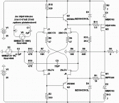
This is my latest foolish attempt. Seems to handle 96KHz at full
output swing without getting all sideways wiggly on me...
The secret bandwidth trick seems to be obscene amounts of
quiescent current rushing past the gates (blame R10) ... And
very small gate stoppers, maybe too small... The P-CH seems
to be the weak link needing 3 times more gate current for the
same bandwidth if RDS-ON is chosen to be equal (9140 rather
than "matching" IRF9240 for equal gate charge, but half an
ohm of extra On resistance). Electrons faster than holes I'm
guessing??? This amount (25mA) of current is overkill for the
N-Channel drive requirement, but the P makes it a necessity...
Its also got the same Schottky AB smoothness. But not the Fork
Voltage gap to explain it... Yes, it works. I'm just not sure why.
Since these MOSFETs have not been Hawksfordized, should still
have all the necessary square law curvature. But add Schottkys
to the party just makes it that much better...
I'll post my .ASC in a sec. But I need to make sure I remember
this time to gather up and include all the non-default models.
Attachments
Member
Joined 2009
Paid Member
It runs nicely !
All I needed to do was add to the schematic two spice directives for the jfet models, namely ".inc 2SK170.mod" and ".inc 2SK170.mod"
not sure about the filename though 🙂
p.s. transient analysis shows a lot of harmonics.
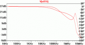
edit: the AC freq response is a bit unusual to my eyes. See attached. The gain is the curve with the little 'peak', looks like phase margin is not huge - or I'm doing something wrong?
Attachments
I have no idea what any of that stuff means. Seriously...
If you want to explain it, I'm listening.
---------------------------------------------------
But let me digress:
I've always thought "Harmonics" a ridiculous way to
describe a non-linear transfer curve. Depending where
(DC) on the curve you sit, you get a completely different
profile.... And when any two signals ride upon another,
you can't describe IMD that way...
I wish to debunk that whole 7th order dissonance thing
that keeps getting repeated. Small whole number over
small whole number fractions are completely consonant.
Does not matter if they describe a note in the 12 tones
we call "notes" or not. A perfectly just note in the circle
of 7th order harmonics is as wholesome as a perfectly
just octave or diatonic fifth (circle of 3rd order harmonics).
You can clip a sine into a square wave, and the result
has plenty of 7th and every other odd harmonic, but is
not dissonant till you try to play two notes that are not
closely harmonically related (as strings of a guitar chord).
When unrelated tones mix, only then it turns to crud.
Same thing if you clip a sine upon its slew.... A Triangle.
You get all the even harmonics, none dissonant, till you
try to put two unrelated tones thru at once....
I'm not sure this "7th order harmonic" that is so feared
is anything other than a measurable symptom of a glitch
in the AB crossing, clipping, ringing, or any other sharp
discontinuity in the transfer curve. It is not evil of itself.
-------------------------
So, I got some 2nd and 3rd harmonics at 1W...
What does that say about the transfer curve?
Try to drive this amp into clipping, and watch it recover.
I think that recovery and smooth AB crossing a lot more
important, and often overlooked..
IRFP9240 substitutes
Ken,
I suggest using FQA12P20 instead of IRFP9240.
See post 18 from Andy.
http://www.diyaudio.com/forums/showthread.php?s=&threadid=89862
-Atiq
Ken,
I suggest using FQA12P20 instead of IRFP9240.
See post 18 from Andy.
http://www.diyaudio.com/forums/showthread.php?s=&threadid=89862
-Atiq
Attachments
Bigun said:It runs nicely !
All I needed to do was add to the schematic two spice directives for the jfet models, namely ".inc 2SK170.mod" and ".inc 2SK170.mod"
not sure about the filename though 🙂
p.s. transient analysis shows a lot of harmonics.
edit: the AC freq response is a bit unusual to my eyes. See attached. The gain is the curve with the little 'peak', looks like phase margin is not huge - or I'm doing something wrong?
It's result of a positive feedback that starts playing role when Ft of bipolar transistors goes down. And remember, it goes down with signal current as well (Kirk effect) that SIM does not show.
Member
Joined 2009
Paid Member
Wavebourn said:It's result of a positive feedback that starts playing role when Ft of bipolar transistors goes down. And remember, it goes down with signal current as well (Kirk effect) that SIM does not show.
Are you saying that it is 'real' and needs to be compensated for ?
Kenpeter: if you are asking me what I mean by harmonics? well it means that when I did the sim, and I put in a sine wave, I don't get a sine wave at the output.
OK, you guys got me confused... What is the Spock effect?
And why are my FTs falling down?
What size and frequency of sine did you put in? There is
some compression in the transfer curve as the magnitude
increases... A compressive transfer function might mimic
nature better than hard clipping, was that a bad choice?
And why are my FTs falling down?
What size and frequency of sine did you put in? There is
some compression in the transfer curve as the magnitude
increases... A compressive transfer function might mimic
nature better than hard clipping, was that a bad choice?
I meant to say beta is going down with frequency, not Ft. Ft goes down due to Kirk effect (widening of base with current).
About positive feedback, gradually decrease Beta of your transistors and see what happens.
About positive feedback, gradually decrease Beta of your transistors and see what happens.
kenpeter said:
What size and frequency of sine did you put in? There is
some compression in the transfer curve as the magnitude
increases... Is that bad?
No, it's not bad. It's low order odd distortions.
I get that the Base emitter junction might be some kind of Varactor?
Is that why the Ft goes down? But I don't get how this is a positive
feedback.
If the base shrinks, the stored varactor charge increases in voltage.
If the base widens, the stored varactor charge decreases in voltage.
Wouldn't that be a Negative feedback?
Is that why the Ft goes down? But I don't get how this is a positive
feedback.
If the base shrinks, the stored varactor charge increases in voltage.
If the base widens, the stored varactor charge decreases in voltage.
Wouldn't that be a Negative feedback?
Member
Joined 2009
Paid Member
Originally posted by Wavebourn No, it's not bad. It's low order odd distortions.
It depends on how you run the sim. I ran it using the paramters as they were downloaded. But you have to be careful with spice as the FFT can pick up some strange ideas if the waveform doesn't start at 0V.
You can get a relatively clean trace by starting at 0s and although it's not quite the full story it gives you a good idea.
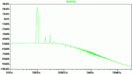
So I cranked it up to 10kHz at 23V input and got the attached FFT. You see some H2 and some H3. Looks much better than my first look-see.
By the way, I'm not a fan of chasing low distortion for the sake of it, I actually prefer some low order harmonics for a 'rounded sound'. In fact I'm usually trying to engineer some H2/H3 into my amplifier 😀
Attachments
Bigun said:
By the way, I'm not a fan of chasing low distortion for the sake of it, I actually prefer some low order harmonics for a 'rounded sound'. In fact I'm usually trying to engineer some H2/H3 into my amplifier 😀
You got some even order harmonics because models of devices are not fully complementary. 😀
Try this one:
http://www.diyaudio.com/forums/attachment.php?s=&postid=1858788&stamp=1245364119
but replace D4 and D5 by 1N5711.
This output stage is bulletproof: it was designed for a guitar hybrid, but it sounds very nice with Hi-Fi amps.
http://www.diyaudio.com/forums/attachment.php?s=&postid=1858788&stamp=1245364119
but replace D4 and D5 by 1N5711.
This output stage is bulletproof: it was designed for a guitar hybrid, but it sounds very nice with Hi-Fi amps.
- Status
- Not open for further replies.
- Home
- Amplifiers
- Solid State
- output buffer for a hybrid amplifier


