sajti - i am really tempted to drop my idea on using the ccs's in the driver of the transistors for some project where they would suit better and to try your buffer.....
hmmmm.
when You would be able to tell a bit about the sound or at least to give us some measurements.....
thanks....
best regards to you all....
daniel
hmmmm.
when You would be able to tell a bit about the sound or at least to give us some measurements.....
thanks....
best regards to you all....
daniel
sajti said:
Triple darlington solve this problem.
Yep. 3'rd order of beta droop. 😎
sajti - can You explain me if i would have those spikes i can see on simulator also in the real ciruit..... probably not - but i would like to know why i have them there (on simulator)... THNX...
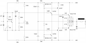
this is the schematic and in the next post will be the instrument measurement....
this is the schematic and in the next post will be the instrument measurement....
Attachments
sajti said:
You have right. The bias stability is worse, than the double darlington. But if You use separated heatsink for the predrivers, the problem is less serious.
My amplifier has 70mA bias for each output device (560mA total), and it's stable with 0R22ohm emitter resistors.
The beta-drop is the most serious problem with the double darlington. So, this means, that the input impedance can drop down to 2-5kohms. This is not acceptable with tube drivers. Triple darlington solve this problem.
Sajti
Hello Sajti
How much warm the predrivers are being ?
Have you try it with a higher value emitter resistors, like 0R33ohm or 0R47ohm ?
Here is the a tube circuit, but I'm not sure it could work with your
Triple darlington circuit ?
Thank
Bye
Gaetan
Attachments
Gaetan, you are coming close to my Tower hybrid amp. 😎
Add direct coupling, bi-polar power, and a CCS load, and you got it. 🙂
Add direct coupling, bi-polar power, and a CCS load, and you got it. 🙂
sajti,
At the expense of linearity. Count on high distortion.Triple darlington solve this problem.
Wavebourn said:Yep. 3'rd order of beta droop. 😎
If You choose wrong device. But for tube VAS You have to use triple darlingtons. I did some tests with double darlington, but drive the output with 6L6 cathode followers, running 50mA, is not so practical...
Another possibility to use more output devices, to avoid beta-drop. So the best devices can handle up to 4-5A without it. This means 2pairs for 100W/8ohm, and the input impedance of this stage will be about 20-80kohms, depends by the load. Youi still need powerful drive
Sajti
sparkle said:insturments are here....
I have no spikes on square waves. But my amplifier use MJE15032/33 as predriver, NJW0281/0302 as driver, and 8 pairs of FJL4215/4315, as output.
So try to modify the base resistor values, or add some 10-100pF C-B capacitors.
Sajti
Lumba Ogir said:sajti,At the expense of linearity. Count on high distortion.
I don't find it. Overloading of the driver tubes makes more distortion, I thnik. Do You have any other experience?
Sajti
sparkle said:sajti (or anybody else)... how about this - regarding the bootstrapping of the resistor divider.... 🙂
That looks OK for me.
Sajti
gaetan8888 said:
How much warm the predrivers are being ?
Have you try it with a higher value emitter resistors, like 0R33ohm or 0R47ohm ?
Here is the a tube circuit, but I'm not sure it could work with your
Triple darlington circuit ?
Hi,
in my first version, I use BC639/640 as predrivers. They can handle 10mA without any additional cooling. The rails are +/-35V. So BD139/140 can handle 10mA as well.
Higher emitter resistor means higher distortion. So I try to keep it as low as possible. (The minimum value depends by the thermal runaway)
This circuit can be OK, but with other tubes. I recommend E88CC, or ECC99. And higher bias. 6-8mA would be OK.
Sajti
sajti said:
I don't find it. Overloading of the driver tubes makes more distortion, I thnik. Do You have any other experience?
I do. each of 3 transistors have Kirk and Early effects. I.e. their base width (hence beta) depends on voltages and currents. When you add one more, multiply their betas (and variations!). Add one more, then multiply on it's variations! As the result, you have variations in the 3'rd power. Yes, an average resistance is higher, but is much more variable.
Not so simple, Sir! There are other methods. 😉
Wavebourn said:
I do. each of 3 transistors have Kirk and Early effects. I.e. their base width (hence beta) depends on voltages and currents. When you add one more, multiply their betas (and variations!). Add one more, then multiply on it's variations! As the result, you have variations in the 3'rd power. Yes, an average resistance is higher, but is much more variable.
Not so simple, Sir! There are other methods. 😉
You have right. But the first stage of the triple darlington can run in class A, close to the constant dissipation, which reduce the temperature related variation.
The input impedance is much higher (close to 1Mohm!). It's change, but if I use resistor load for the tube driver the overall changes will be negligible.
I tried som other methods:
- feedback in the output stage. It works, but can be unstable, if I use as much feedback as enough to reduce the distortion
- double darlington It works, but the driver stage will be more complicated (high current cathoda follower), or I have to use feedback in the driver stage
- SE class A BJT predrivers It works, but I have to use DC servó to avoid the offset resulted by temperature changes
Sajti
Very clean and fast SE BJT driver, class C outputs. Like Current Dumping. You've seen my Swinik. Now, imagine a 2-tube amp instead of an opamp.
sajti said:
I have no spikes on square waves. But my amplifier use MJE15032/33 as predriver, NJW0281/0302 as driver, and 8 pairs of FJL4215/4315, as output.
So try to modify the base resistor values, or add some 10-100pF C-B capacitors.
Sajti
i'll do that later today... my sims are at my home pc...
sajti said:
That looks OK for me.
Sajti
thank You - it looks also to me but i wanted to be sure... 🙂
Wavebourn said:
Not so simple, Sir! There are other methods. 😉
can You recomend some of them please - thanks.....
===========================================
o.k. so far we have two of the circuits in here....
- one that is using double dralington and a ccs in each driver transistor emitter... that one looks o.k. but has to get a front end that has "a lot" of current to be able to drive this output.... somehting like some crazy triode or a penthode with at least 30mA of plate current...
- the second one is the one that is proposed by Sajti - the one is using tripple darlington - that one is "easier" to drive and should also have a good results with a "normal" fron end like one stage plate follower using 5687 or similar.....
right??
can we still consider NSCA circuit... i couldn' make it work in the simulator - it is also a tripple darlington output...?? schematic is here in post 29
http://www.diyaudio.com/forums/showthread.php?postid=1857049#post1857049
=================================
guys - thank You for giving attention to this thread.... Your help is very valuable.... thank You... i am happy... 😀
sajti - how about an idea...
looking at your schematic - would it be nice to put a ccs in each emiter of the predriver tranistors (like i have suggested for driver transistors)... or maybe to do that on driver transistors in Your schematic??....
what do You think ???
looking at your schematic - would it be nice to put a ccs in each emiter of the predriver tranistors (like i have suggested for driver transistors)... or maybe to do that on driver transistors in Your schematic??....
what do You think ???
sparkle said:sajti - how about an idea...
looking at your schematic - would it be nice to put a ccs in each emiter of the predriver tranistors (like i have suggested for driver transistors)... or maybe to do that on driver transistors in Your schematic??....
what do You think ???
It's possible to do. I don't use it, because I use no PCB, so I always try to keep it simple...
Sajti
- Status
- Not open for further replies.
- Home
- Amplifiers
- Solid State
- output buffer for a hybrid amplifier