WOW 
thnx CBS240.....
it will be a of a problem to implement this into the circuit that is allready proposed in post no. 16 of this thread.... i will read the article and see what i can do.... thanks again 😀
thnx CBS240.....
it will be a
of a problem to implement this into the circuit that is allready proposed in post no. 16 of this thread.... i will read the article and see what i can do.... thanks again 😀the biggest problem with the circuit from post no.16 is to maintain ballance in order not to have a dc offset at the output.... that is a of a problem....
it would be nice to come up with something to balance the circuit naturally - without the dc offset correction using opamp
of a problem....it would be nice to come up with something to balance the circuit naturally - without the dc offset correction using opamp
I did some test, but unfortunately 2stage darlington is not enough. You need the driver tube 30-40mA biased. So I think, that triple darlington is mandatory
Sajti
Sajti
Member
Joined 2009
Paid Member
Sparkle,
It's coming along very nicely as far as I can tell.
Probably is worth taking a closer look at how much load the output buffer is presenting to the tube front end. My friend bought one of those chinese hybrids with ClassAB SS output. It sounded pretty muffled. The issue turned out to be related to overloading of the front end so he had to modify it somewhat. He didn't have to change the SS output though, but the front end had to be configured to drive the output which is based on two parallel output devices to deliver 85W.
I did some test, but unfortunately 2stage darlington is not enough. You need the driver tube 30-40mA biased. So I think, that triple darlington is mandatory
Sajti
Hello Sajti
I've read somewhere that the triple Darlinton output stage is more likely to suffer Vbias stability problems and exhibits greater susceptibility to beta-droop problems.
What is your POV about that ?
Thank
Bye
Gaetan
sajti said:I did some test, but unfortunately 2stage darlington is not enough. You need the driver tube 30-40mA biased. So I think, that triple darlington is mandatory
Sajti
Sajti - thnx for taking additional tests - very nice of You...
getting 30mA from a front tube stage is not a problem - there are more than few ways and tubes how to do it.... so, i do not worry about that - i only would like to decide for now that this or that output stage should be used .... 😀
Bigun said:Sparkle,
It's coming along very nicely as far as I can tell.
Probably is worth taking a closer look at how much load the output buffer is presenting to the tube front end. My friend bought one of those chinese hybrids with ClassAB SS output. It sounded pretty muffled. The issue turned out to be related to overloading of the front end so he had to modify it somewhat. He didn't have to change the SS output though, but the front end had to be configured to drive the output which is based on two parallel output devices to deliver 85W.
yes it is progressing nice...
- i assume, also, that the biggest problem in hybrids, is making front end and output work together in harmony - not to overload the front end in order to get the best out of it.....
....
the other thing that is bothering me with all the designs proposed here is the dc offset correction... it is usually made by using a trimmer in the positive rail, over the Vbe multiplier or biasing diodes and with that resistor we correct the dc offset.... i am affraid that this method is MAYBE not good enough.... and i would like not to use opamp from output to input to correct the dc offset.... so, regarding that question - i really do not know what to do... is anybody having any ideas about that.....thnx....
one output stage that is also really interesting to me is the NSCA output stage made by Bartolomeo Aloia and used on this site ....
http://www.marignoni.it/ElettronicaHiFi/BlacksmithTheWithe/BlacksmithTheWithe.JPG
(do not look here at the rest of the schematic but only the output stage)... very interesting - those ccs's don't allow the output devices to turn of... but i couldn't make it work - i can't bias the current thorugh the output devices lower than 300mA... so if somebody has any opinions about this one or a way how to make it work (it is suposed to work like that)... i do not know....
butthe feature of not turning the output devices of is certainly interesting.....
here is the simulator pdf file.....
Attachments
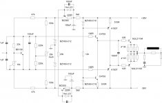
looking at the page http://www.wimdehaan.nl/hybrid/6463hyb/index.html i came on the idea to try the dc correction circuit like proposed there...
it seems to be working - and the bandwidth of the amplifier increased a lot - don't know f i can trust that .. (i tried that in the sim and as we all know thy are not so perfect and accurate) ....
so here it is - the next version of the amp from the post no16.
NSCA is still under consderation - if it might work it will be also nice to get the output transistors not to switch of.... oh well.....
opinions please....
thnx...
Attachments
i have seen that i have the same post twice... i am sorry about that... i had some problems with posting that particular post....
hopefully moderators can clear that out.... thanks.....
i am refering to post 30 and 31...
hopefully moderators can clear that out.... thanks.....
i am refering to post 30 and 31...
Member
Joined 2009
Paid Member
Originally posted by sparkle the other thing that is bothering me with all the designs proposed here is the dc offset correction... it is usually made by using a trimmer in the positive rail, over the Vbe multiplier or biasing diodes and with that resistor we correct the dc offset.... i am affraid that this method is MAYBE not good enough....
My friends hybrid also uses this scheme, the problem is that way it is implemented means the output stage bias and dc offset are not independent controls and you have to fiddle with both of them when setting it up. However, it does work and he was able to get a very low dc offset (you have to set it up when the amplifier is at normal operating temperature)
I like the NSCA idea, I tried to make a design like this a couple of weeks ago but couldn't get it to work and gave up. I didn't have the NSCA design as a starting point though. I have no idea if it's proven to improve sound quality.
Bigun said:
My friends hybrid also uses this scheme, the problem is that way it is implemented means the output stage bias and dc offset are not independent controls and you have to fiddle with both of them when setting it up. However, it does work and he was able to get a very low dc offset (you have to set it up when the amplifier is at normal operating temperature)
I like the NSCA idea, I tried to make a design like this a couple of weeks ago but couldn't get it to work and gave up. I didn't have the NSCA design as a starting point though. I have no idea if it's proven to improve sound quality.
i know - it is a bit complicated to set the bias and dc offset - but it should work.... i think that the dc offset network in post no. 31 is a bit more "relaxed" way to do it... i was playing a bit with it and found the correct values of the resistors with no problems ......... i will post that sch tommorow too..... 😀
I was also not able to make the NSCA design to work in the simulator ... the designer of the Blacksmith amplifier, Fabrizio, tells me that the design is correct but the problem is probably in the simulator that "simulator cannot “hear” the difference among switching and non switching operating. "... but he is telling me that it is working - Blacksmith is not made but the output IS and it should work - this would be nice to have the switching problem removed....
argghhh...
this is a thing to do....o.k. - i have to rethink everything and i will come back .... 😀 stay tuned and thanks for every help You guys did provide.... thnx...
sparkle said:i played a bit with noise cancelation CBS240 proposed...
i still think that post no.16 is better way to go....
in attachement of this post is the sch. i was playing with..... 😀
The idea is not do much noise cacelation, but correction of the non-linear components that are related to the Darlington output devices. The error amplifier transistors or rather one of them, Q3 or Q5, can be mounted to the heatsink with the outputs to control thermal bias changes.
There is a more practical application of this circuit, used to drive those non-linear hex-fet type devices by Bob Cordell, here.
Member
Joined 2009
Paid Member
Originally posted by sparkle I was also not able to make the NSCA design to work in the simulator ... the designer of the Blacksmith amplifier, Fabrizio, tells me that the design is correct but the problem is probably in the simulator that "simulator cannot “hear” the difference among switching and non switching operating. "
Ah yes, the bane of all us, still waiting for a spice model for the human ear
😀
gaetan8888 said:I've read somewhere that the triple Darlinton output stage is more likely to suffer Vbias stability problems and exhibits greater susceptibility to beta-droop problems.
You have right. The bias stability is worse, than the double darlington. But if You use separated heatsink for the predrivers, the problem is less serious.
My amplifier has 70mA bias for each output device (560mA total), and it's stable with 0R22ohm emitter resistors.
The beta-drop is the most serious problem with the double darlington. So, this means, that the input impedance can drop down to 2-5kohms. This is not acceptable with tube drivers. Triple darlington solve this problem.
Sajti
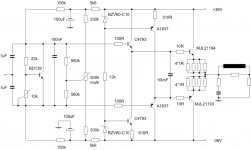
sparkle said:and also this version is here too...
opinions???
The input iimpedance of this buffer is less, than 20kohm, without any load connected. So it's not useful for tube driver.
What I found:Bootstrapped bias resistor string easily set the output close to 0. My amplifier has less, than 20mV offset with hot or cold heatsink. The input impedance is approx 70kohm, with 2ohms load.
Sajti
CBS240 said:
The idea is not do much noise cacelation, but correction of the non-linear components that are related to the Darlington output devices. The error amplifier transistors or rather one of them, Q3 or Q5, can be mounted to the heatsink with the outputs to control thermal bias changes.
There is a more practical application of this circuit, used to drive those non-linear hex-fet type devices by Bob Cordell, here.
thanks for the link - much appreciated.... i will read it 😀
Bigun said:
Ah yes, the bane of all us, still waiting for a spice model for the human ear
😀
😀 heheheheheh - right......
sajti said:
You have right. The bias stability is worse, than the double darlington. But if You use separated heatsink for the predrivers, the problem is less serious.
My amplifier has 70mA bias for each output device (560mA total), and it's stable with 0R22ohm emitter resistors.
The beta-drop is the most serious problem with the double darlington. So, this means, that the input impedance can drop down to 2-5kohms. This is not acceptable with tube drivers. Triple darlington solve this problem.
Sajti
o.k. Sajti - thanks.... i understand it now a bit better.....
o.k.... i am happy that we are progressing....
thank You..
sajti said:
The input iimpedance of this buffer is less, than 20kohm, without any load connected. So it's not useful for tube driver.
What I found:Bootstrapped bias resistor string easily set the output close to 0. My amplifier has less, than 20mV offset with hot or cold heatsink. The input impedance is approx 70kohm, with 2ohms load.
Sajti
i also don't like that one... to complicated..... however i do like your output and it is still in the game.... ... just checking all the options to better decide... thank You for info....
- Status
- Not open for further replies.
- Home
- Amplifiers
- Solid State
- output buffer for a hybrid amplifier