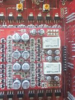
It may be nothing more than a sort of a shield between the adjacent traces. Look at how it wraps around from the larger (ground?) trace.

Perfect that does make sence.
Do you know what this section is likey to be, I know there are no schematics but mabey you recognise the layout/components ?

Also I'll add in a larger photo of that trace. Noticed the pic I posted had a but cut off.
And 3rd do you know the reason for these relays? The output on the terminals will kick in before these relays do so a bit confused on there purpose as everything kicks in before they do🤨 (on output driver card)
Just courious is all🙂


Do you know what this section is likey to be, I know there are no schematics but mabey you recognise the layout/components ?
Also I'll add in a larger photo of that trace. Noticed the pic I posted had a but cut off.
And 3rd do you know the reason for these relays? The output on the terminals will kick in before these relays do so a bit confused on there purpose as everything kicks in before they do🤨 (on output driver card)
Just courious is all🙂
Attachments
I have nothing resembling the circuit with the relays.
The 2N7000 FETs are commonly used with optocouplers in protection circuits. I don't have anything that has the same circuit board designations as your amp so I can't say how your are used.
The 2N7000 FETs are commonly used with optocouplers in protection circuits. I don't have anything that has the same circuit board designations as your amp so I can't say how your are used.
Perry could you please answer a question I have in regards to class A/B.
Am I correct in thinking you will never see any type of drive wave on any of the output transistors on a class A/B using an oscilloscope? (Like you do on class D)(Injecting let's say 60Hz.)
You will only see plus and minus voltages..
It's only class D that you will?
I learned on class D. So having a bit of trouble tracing around trying to find why i have no audio.
All drivers and pre amp checks out as I can see injected signal there however driver board seems to be missing voltages.
Example all the capacitors show 0v even when powered on. The +-5v +-6 +-16 regulators are all working correctly.
Thanks
This is a VERY complex amplifier and being unfamiliar with it I can't help with specifics.
For class D amplifiers, you know that the high-side drive can either be full rail-rail (all N-channel configuration) or it can be just 10v from the high-side rail (for amps that use P-channel FETs for the high-side).
The same thing applies to linear mode (not switch-mode, class D...) amplifiers You can have a follower (common collector amplifier) where the high-side collector is connected to the rail voltage. For those, you will see a drive on the base that's approximately the same amplitude as the output to the speakers (on the emitter). For common emitter amplifiers (emitter on the rails), you may see little or no signal on the base, even though the amp is driven to full power.
A good place to look for signals is on the headers of an amp. If the signal never leaves the preamp board/section, it's not going to be seen any farther down the line.
Do you have any other amps in the shop to check for signal levels so you know what to look for?
No similar amps. Only have an old clarion that's working. (Class A/B)
Only other Orion hcca is the 8000 class D that's not working.
All my amps here are class D.
I can see the pre amp working as I see the correct voltages plus I can see the signal going into input A and B and also on the output A and B.
I just can't see anything on any of the pins going into the output driver board (the one with the relays)
Only see plus minus 35+ volts( I didn't adjust my scope screen to allow me to see the full volatge here as I was only looking for signal and smaller voltages under 25v.
But it may be that very high voltages go up to here then get lowered for driver chips 🤷.
But yeah i can't see any 60hz up there....
Follow the traces from the preamp board towards the large driver board. Where do you lose signal.
If the signal from the preamp directly feeds the inverting input of an op-amp or a differential amplifier, you may see no signal on either of those inputs. To see the signal, you have to look at the resistor that feeds them. So, the signal either isn't reaching the board or is feeding an inverting input.
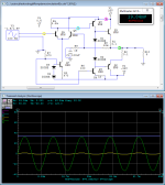
The following is for a previous question but it shows both the signals mentioned. The VAS stage is a common emitter and you can see waveform B is very low (the meter reading, 19.84mv) but the output from its collector is approximately the same as the output signal on the output stage of the amplifier, which is a common collector. For a common emitter, you may see very little signal. For common collectors, you have a follower and the drive amplitude is approximately the same as the output amplitude.
If the signal from the preamp directly feeds the inverting input of an op-amp or a differential amplifier, you may see no signal on either of those inputs. To see the signal, you have to look at the resistor that feeds them. So, the signal either isn't reaching the board or is feeding an inverting input.
The following is for a previous question but it shows both the signals mentioned. The VAS stage is a common emitter and you can see waveform B is very low (the meter reading, 19.84mv) but the output from its collector is approximately the same as the output signal on the output stage of the amplifier, which is a common collector. For a common emitter, you may see very little signal. For common collectors, you have a follower and the drive amplitude is approximately the same as the output amplitude.
Attachments
- Home
- General Interest
- Car Audio
- Orion HCCA 4 channel