The regulator will only short once I apply 12v remote.
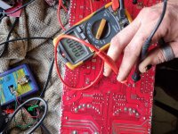
As for the rail caps I'm not sure but here are photos showing they are infact shorted. No volatge in the board when I took these photos and probes were on for a good 40 seconds before taking photo.
Please excuse the horrible photography it's hard to hold probes and take a photo

As for the rail caps I'm not sure but here are photos showing they are infact shorted. No volatge in the board when I took these photos and probes were on for a good 40 seconds before taking photo.
Please excuse the horrible photography it's hard to hold probes and take a photo
Attachments
If you power up the amp, does the voltage there remain at 0v?
Where did you measure 38v of rail voltage?
Where did you measure 38v of rail voltage?
I measured 38V on the output transistor.
There is only a short on the rail caps when power is in the board. It appears.......
I just removed the LM337 and my tester is saying it's faulty...
With power in the board I'm reading 38v on all rail caps... so I guess there not shorted....
I'll order this LM33 and see what it improves
There is only a short on the rail caps when power is in the board. It appears.......
I just removed the LM337 and my tester is saying it's faulty...
With power in the board I'm reading 38v on all rail caps... so I guess there not shorted....
I'll order this LM33 and see what it improves
Do you have rail voltage (positive and negative) on all of the output transistors?
Without Q713, what's the DC voltage on pin 18 of the 3526?
Without Q713, what's the DC voltage on pin 18 of the 3526?
I only seem to have negative voltage on the outputs.
Pin 18- 7.34vDC
IC88 (LM33) has been removed
Pin 18- 7.34vDC
IC88 (LM33) has been removed
With all components fitted I'm seeing a DC bump on start up on front channels only.
Also I'm getting a few outputs showing -3v and some +3V. with a consistent negitve 28vDC on all middle legs (collector?)
Also I'm getting a few outputs showing -3v and some +3V. with a consistent negitve 28vDC on all middle legs (collector?)
Is it possible that your meter is reading 0.0 ohms when it sees voltage (possibly negative voltage) when it's set to ohms?
Does this amp have both positive and negative rectifiers?
Does this amp have both positive and negative rectifiers?
Yes it has 2 on one side of the board and 2 opposite side of board.
This multimeter is brand new to me still getting used to it. Would love to continue to use my old one however it's just too old now
This multimeter is brand new to me still getting used to it. Would love to continue to use my old one however it's just too old now
What makes it too old? I have meters that are from the mid 1980s and they serve the purpose perfectly.
The probes no longer insert into it and make solid contact. I just opted to buy a new meter. But i may just buy new probes for my old meter as this new one is sending me in the wrong direction quiet a bit.
Perry. On a class A/B. Should I be getting a pretty close match of positive and negative rail on the output transistors?
As I'm seeing -28vDC but only +3vDC.
As I'm brand new to class A/B I'm not sure if this is normal. I am getting audio out of the rear so suspect it may be normal.
I'm thinking I may pull all driver boards for the front channels and check components. Next to impossible to do with board attached.
My limited skill is suggesting there is a short circut on one of these boards.
Thanks 🙂
It's most definitely not common to have only one rail and especially only a negative rail. Use the secondary center tap on the transformer for the reference (black probe). You can also use the non-bridging terminals.
Are you checking for rail voltage on the output terminals of the rectifiers?
Are you checking for rail voltage on the output terminals of the rectifiers?
All testing has been done using my oscilloscope with ground on main input ground. DC coupling.
I did a small test with my multimeter just putting probes on the legs of the output transistors.
I'm just letting you know this info so that if anything I've brought up in this post may be attributed to having my scope ground on main ground.
On the rectifiers is the ground always the >[]< or <[]>? If you could help me with that question that may better help me find the centre tap of the transformers
Thanks perry
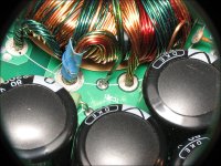
The secondary side of the transformer will be on the audio side of the transformer. The secondary has two bundles of wires of two different colors. Where those two colors are combined is the center-tap.
The attached is not an Orion but it's the same layout. Yellow and green windings on the outside (go to rectifier inputs) and the combined windings, which are the center-tap.
The attached is not an Orion but it's the same layout. Yellow and green windings on the outside (go to rectifier inputs) and the combined windings, which are the center-tap.
Attachments
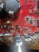
Negative probe on here which is a direct connection to non bridged negative speaker terminal I'm now seeing both plus and minus 38v DC rails. On all output transistors.
I'm seeing what I would suspect as normal (ie) base collector and emmiter I'm seeing 0v base. 38vDC collector 0v emmiter. Or 38vDC base 0v collector 38v collector. So there are no voltages where there shouldn't be. In regards to output transistors
I'm seeing what I would suspect as normal (ie) base collector and emmiter I'm seeing 0v base. 38vDC collector 0v emmiter. Or 38vDC base 0v collector 38v collector. So there are no voltages where there shouldn't be. In regards to output transistors
Attachments
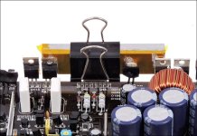
These LM voltage regulators are getting hot quiet fast. Too hot to touch.
Q713 is removed from circut
2.3Amps of idle current

Q713 is removed from circut
2.3Amps of idle current
- Home
- General Interest
- Car Audio
- Orion HCCA 4 channel