I checked again with ATC and the 16 ohm mid is in BOTH the passive and the active. I am thinking to annoy the missus 😀 and buy the active amp units.
Regards
CL
Regards
CL
I had ordered mine from Wilmslow without crossovers and went with ATC active crossover/amp units.
I had ordered mine from Wilmslow without crossovers and went with ATC active crossover/amp units.
Hi how much are the the active crossovers?
I had ordered mine from Wilmslow without crossovers and went with ATC active crossover/amp units.
Did the standard midrange from the Wilmslow kit work perfectly with the active crossover? I was wondering if the lower grade midrange has the same resistance, sensitivity as the super mid the active xovers were made to match.
Hi how much are the the active crossovers?
I bought mine used at the swap meet here. They came from SCM150 Anniversary monitors. I had to supply them with heatsinked cases.
The mids that wilmslow supply are the standard 16 ohm version which are what was used in the original scm 100s. The amp pack work perfectly with the stadard 16 ohm mids like in the wilmslow kit or in older scm100s, or the super mids (I asked ATC). If you really wany the super mids you can always buy the kit minus the standard mids and buy the sl versions from ATC from memory 365 pounds each, but thr RD guy said by far the money best spent is on the amp packs and going active, not upgrading the mids.Did the standard midrange from the Wilmslow kit work perfectly with the active crossover? I was wondering if the lower grade midrange has the same resistance, sensitivity as the super mid the active xovers were made to match.
Regards
CL
Does anyone know the correct polarity of the drivers ect in the diagram?I have got the XO from internet but I can't remember the site.
Thanks
CL
It appears to me that the "top" of the circuits in the diagram are the + sides, since that's where the inductors and caps are shown, and the bottom lines are pretty much plain lines, which would indicate the - ground side. BUT, I am guessing.
Thanks, it is what I thought too, but again I am not sure either.It appears to me that the "top" of the circuits in the diagram are the + sides, since that's where the inductors and caps are shown, and the bottom lines are pretty much plain lines, which would indicate the - ground side. BUT, I am guessing.
Anyone know for sure?
Regards
CL
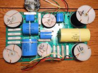
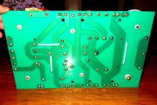
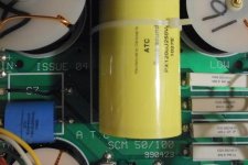
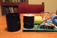
I'm thinking it might be useful for a person wanting to build their own passive crossover to see where ATC laid out the components. I've read where it can be difficult to bring a schematic to life. The bottom of the board shows the same orientation as the top. I just tipped up the board.
Attachments
-
 alarm clock atc xover closeup 015.jpg1,004.3 KB · Views: 943
 -
 alarm clock atc xover closeup 017.JPG230.2 KB · Views: 824
 -
 alarm clock atc xover closeup 014.JPG258.8 KB · Views: 779
 -
 alarm clock atc xover closeup 013.JPG277.5 KB · Views: 770
 -
 alarm clock atc xover closeup 012.JPG300.4 KB · Views: 786
 -
 alarm clock atc xover closeup 011.JPG231.8 KB · Views: 361
 -
 alarm clock atc xover closeup 016.JPG255.5 KB · Views: 414
Hello ewhitaker!
many thanks for the photos!
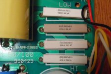
But the value of the resistors is different than the schematic of posting 3 of first page.
Do you think that there is only a adjustment for the Seas tweeter?
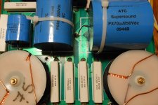
Can you measure the exact value of the coils?
Regards
Seyed
many thanks for the photos!
But the value of the resistors is different than the schematic of posting 3 of first page.
Do you think that there is only a adjustment for the Seas tweeter?
Can you measure the exact value of the coils?
Regards
Seyed
Seyed, A representative at Flat Earth Music (North America ATC distributor) told me the crossover is the same with both tweeters. I would be happy to measure the coils, but can I do that when they are soldered into the circuit? Possibly the schematic is a different generation than the design I have? If there is a way to measure the inductors in circuit, help me through it and I will do so.
Helloewhitaker !
Unfortunately you have to unsolder the coil to measure it.If you have a multimeter with optional to imeasure inductive .
Regards
Seyed
Unfortunately you have to unsolder the coil to measure it.If you have a multimeter with optional to imeasure inductive .
Regards
Seyed
I am guessing the values written on the coils are the inductance values.Helloewhitaker !
Unfortunately you have to unsolder the coil to measure it.If you have a multimeter with optional to imeasure inductive .
Regards
Seyed
Regards
Chris
Hi ewhitaker,
If it would not be too much of a bother, could you take another picture of the PCB from the underside but ideally with light shining through? It makes it easier to get a sense of the two traces - top and bottom. Not sure if this would work, but holding to a window might work.
Cheers and thanks for posting the pictures - already I am seeing some differences with the your xover and the published one.
Hmm strange.. I cant get the first pic to open bigger, the one with the whole board, maybe the link is broken? Any chance of reposting it so we can work out the circuit?
Regards
Chris
Regards
Chris
Hmm strange.. I cant get the first pic to open bigger, the one with the whole board, maybe the link is broken? Any chance of reposting it so we can work out the circuit?
Regards
Chris
The whole board picture opens up when I checked. I didn't resize the original image so if the icon at the lower left of the enlarged picture is clicked on, it really opens up and defeats the need for looking at the other images, IMO.
Really odd as it does not on my computer and it did yesterday (the pic of the front of the board not the rear). All the other pics open up no problem. Any chance you could post another link to that pic so I can try to work out the board?The whole board picture opens up when I checked. I didn't resize the original image so if the icon at the lower left of the enlarged picture is clicked on, it really opens up and defeats the need for looking at the other images, IMO.
Thanks
Chris
- Home
- Loudspeakers
- Multi-Way
- original crossover schematics for clone ATC SCM 100