Progress Report
Hi Doug and Happy New Year to all,
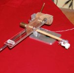
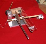
At last I'm back to the LT arm. Last report had me putting the LT aside for cogitation. Holidays are over now and back to the drawing board. Came up with a way to use the V groove glass trak and a flat glass dust protector and set it all up using discarded hardware from other experiments. It is all clear from the pictures. Built a new light weight carriage and all is solidly mounted. I'm really getting enthusiastic about this design now. This model really sounds great. The cylindrical member which holds the trak is mounted by a single screw which permits easy leveling of the trak. Loosen the screw a tad and twist the trak until the level says you are on and tighten the screw. With a few changes the visuals should improve even more. As seen in the pictures it still needs some work, but the concept is there. I'm trying to keep it close to Bo's design but with a few changes here and there.
Bill
BillG,
First, Merry Christmas to you and all the other DIYers out there. It's been an interesting year and I'm looking forward to more developments in the new year.
I read your recent post on the Schroeder thread. While you have your camera out, would you take a couple of shots of your LT and post them, too. I bet I'm not the only one who would like to see them.
Hi Doug and Happy New Year to all,
At last I'm back to the LT arm. Last report had me putting the LT aside for cogitation. Holidays are over now and back to the drawing board. Came up with a way to use the V groove glass trak and a flat glass dust protector and set it all up using discarded hardware from other experiments. It is all clear from the pictures. Built a new light weight carriage and all is solidly mounted. I'm really getting enthusiastic about this design now. This model really sounds great. The cylindrical member which holds the trak is mounted by a single screw which permits easy leveling of the trak. Loosen the screw a tad and twist the trak until the level says you are on and tighten the screw. With a few changes the visuals should improve even more. As seen in the pictures it still needs some work, but the concept is there. I'm trying to keep it close to Bo's design but with a few changes here and there.
Bill
Attachments

OK, I'm starting to shop for parts - a couple more questions
1) how long should the glass tube/glass V carrier?
2) is the distance from the bearings to the arm critical?
3) is arm length of best kept as short as possible?
4) is it better to have as light weight as possible a carriage?
5) what dims of bearing are people using? I'm looking at some 6id x 15od x 5mm
Thanks in advance
Last edited:
measurements
Hi JRKO,
Welcome and fun and good luck etc, etc. You can get a rough set of dimensions from almost any of the arm photos published in this thread by making some assumptions about known parts shown. For example call the distance between center lines of the cartridge mounting screws is 1/2". The distance from the outer groove to the inner grove on the disk will be something a bit more than 3". From the edge of the record to the label, about 4". The actual length of the tone arm wand can be anything, determined on where you want the glass track to sit relative to the edge of the record. The closer to the edge of the record, the easier it will be to change the record without crashing into the arm. So draw a full size plinth and platter sketch and layout something that suite your fancy. Then make some paper dolls of the parts and move them around as though they were actually playing a record. It is almost impossible to get a non functioning arm if you think it through and visualize how the parts work together.
I have found virtually nothing to be critical except for VTA, cartridge alignment, 90 deg from record surface (azimuth) and stylus tangent to the groove.
The following are the actual measurements of the arm in my photos:
Distance between bearing center lines 2"
Stylus tip to carriage 5"
Carriage to back extension of arm wand 2" (to hold counterweight)
Length of glass track 7"min Mine was about 9" but I dropped it, CRASH.
For bearings, mine are about the same as yours but I have OD=10mm, same ID and thickness.
For height of glass track I measure .300"
I think that a critical thing to watch for is the smoothness of the bearing outer race on the actual corner that rides on the glass track surface. A finger nail test should do. Reject any that exhibit scratchiness or nicks.
I have kept the weight of the carriage very light, Photos of the real Cantus show a heavier one.
For the arm wand length, I don't know what the trade-offs are. Maybe DTUT can comment on this, but I'm sure 5" is not too long. Cantus will scale a bit shorter (I think).
So there you have it. My arm is performing beautifully, I am amazed by how well it works and sounds. Let us know how you are doing.
BillG
OK, I'm starting to shop for parts - a couple more questions
1) how long should the glass tube/glass V carrier?
2) is the distance from the bearings to the arm critical?
3) is arm length of best kept as short as possible?
4) is it better to have as light weight as possible a carriage?
5) what dims of bearing are people using? I'm looking at some 6id x 15od x 5mm
Thanks in advance
Hi JRKO,
Welcome and fun and good luck etc, etc. You can get a rough set of dimensions from almost any of the arm photos published in this thread by making some assumptions about known parts shown. For example call the distance between center lines of the cartridge mounting screws is 1/2". The distance from the outer groove to the inner grove on the disk will be something a bit more than 3". From the edge of the record to the label, about 4". The actual length of the tone arm wand can be anything, determined on where you want the glass track to sit relative to the edge of the record. The closer to the edge of the record, the easier it will be to change the record without crashing into the arm. So draw a full size plinth and platter sketch and layout something that suite your fancy. Then make some paper dolls of the parts and move them around as though they were actually playing a record. It is almost impossible to get a non functioning arm if you think it through and visualize how the parts work together.
I have found virtually nothing to be critical except for VTA, cartridge alignment, 90 deg from record surface (azimuth) and stylus tangent to the groove.
The following are the actual measurements of the arm in my photos:
Distance between bearing center lines 2"
Stylus tip to carriage 5"
Carriage to back extension of arm wand 2" (to hold counterweight)
Length of glass track 7"min Mine was about 9" but I dropped it, CRASH.
For bearings, mine are about the same as yours but I have OD=10mm, same ID and thickness.
For height of glass track I measure .300"
I think that a critical thing to watch for is the smoothness of the bearing outer race on the actual corner that rides on the glass track surface. A finger nail test should do. Reject any that exhibit scratchiness or nicks.
I have kept the weight of the carriage very light, Photos of the real Cantus show a heavier one.
For the arm wand length, I don't know what the trade-offs are. Maybe DTUT can comment on this, but I'm sure 5" is not too long. Cantus will scale a bit shorter (I think).
So there you have it. My arm is performing beautifully, I am amazed by how well it works and sounds. Let us know how you are doing.
BillG
Last edited:
more!
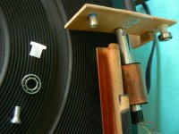
Time for a few more words to update this post. What doesn't show in the pics is the 2 steel blocks that hold this thing in place on the plinth. They just sit on the arm baseplate and weight it all down. The overall configuration works well enough but VTA could only be adjusted by shimming under the base. Also the arm could easily be moved out of position. I have been reluctant to bolt it to the plinth which is a nice piece of faux granit Corian. When all prototyping is done and a finished arm is ready, then I will make holes in the plinth unless I can glue it down. So to stabilize the arm and provide some adjustments I sharpened 3 #8x32 SS machine screws. Then drilled and tapped 3 holes in the baseplate, One at the front and one each at the rear on either side of the upright column. Lock nuts on each screw. Now we have adjustable spikes. Adjustment can now be done for azimuth, VTA, height of arm above platter with the 3 screws. The points on the screws hold it on position against pretty harsh jolts. Eventually there will be a threaded mounting screw clamping the arm to the plinth wjth the spikes still in their adjusted positiion.
After all that description what has changed in operation? The arm is firmly located. It doesn't move in normal operation and then some. The skips and jumps and other tracking problems are GONE! It tracks at lower stylus pressures. The bass is fuller and cleaner not just louder. The consonants are crisper and cleaner. No trace of sibilance. What can I say. It is a joy to listen to. As one would expect with linear tracking, the sound is constant all the way across the record. Those 3 screws, the better build quality and more careful setup alignment (not difficult or time consuming) have resulted in something special. So far my cost other than time is a measly $20 for bearings. The rest came out of the junk box.
Bill
Hi Doug and Happy New Year to all,
At last I'm back to the LT arm. Last report had me putting the LT aside for cogitation. Holidays are over now and back to the drawing board. Came up with a way to use the V groove glass trak and a flat glass dust protector and set it all up using discarded hardware from other experiments. It is all clear from the pictures. Built a new light weight carriage and all is solidly mounted. I'm really getting enthusiastic about this design now. This model really sounds great. The cylindrical member which holds the trak is mounted by a single screw which permits easy leveling of the trak. Loosen the screw a tad and twist the trak until the level says you are on and tighten the screw. With a few changes the visuals should improve even more. As seen in the pictures it still needs some work, but the concept is there. I'm trying to keep it close to Bo's design but with a few changes here and there.
Bill
Time for a few more words to update this post. What doesn't show in the pics is the 2 steel blocks that hold this thing in place on the plinth. They just sit on the arm baseplate and weight it all down. The overall configuration works well enough but VTA could only be adjusted by shimming under the base. Also the arm could easily be moved out of position. I have been reluctant to bolt it to the plinth which is a nice piece of faux granit Corian. When all prototyping is done and a finished arm is ready, then I will make holes in the plinth unless I can glue it down. So to stabilize the arm and provide some adjustments I sharpened 3 #8x32 SS machine screws. Then drilled and tapped 3 holes in the baseplate, One at the front and one each at the rear on either side of the upright column. Lock nuts on each screw. Now we have adjustable spikes. Adjustment can now be done for azimuth, VTA, height of arm above platter with the 3 screws. The points on the screws hold it on position against pretty harsh jolts. Eventually there will be a threaded mounting screw clamping the arm to the plinth wjth the spikes still in their adjusted positiion.
After all that description what has changed in operation? The arm is firmly located. It doesn't move in normal operation and then some. The skips and jumps and other tracking problems are GONE! It tracks at lower stylus pressures. The bass is fuller and cleaner not just louder. The consonants are crisper and cleaner. No trace of sibilance. What can I say. It is a joy to listen to. As one would expect with linear tracking, the sound is constant all the way across the record. Those 3 screws, the better build quality and more careful setup alignment (not difficult or time consuming) have resulted in something special. So far my cost other than time is a measly $20 for bearings. The rest came out of the junk box.
Bill
Last edited:
quick question if I may.
I've got some 6mm carbon fibre tubing that I was planning to use connecting the bearing to the arm. The bearings are 6mm also but they are not a tight fit. Did everyone get a push fit or bond their bearing/rods together?
Ta
I've got some 6mm carbon fibre tubing that I was planning to use connecting the bearing to the arm. The bearings are 6mm also but they are not a tight fit. Did everyone get a push fit or bond their bearing/rods together?
Ta
I'm going to work my way down this last page.
DD - Thanks for the big Cantus picture - it makes the job of figuring dimensions and proportions much easier. That LT has to be the benchmark for all other efforts.
Nanook - Thanks for the info on bearings, especially the tolerances of the different grades. I've had pretty good luck with RC car bearings. Recently, I made a run in jig and put about 30 hours on a couple of them. I chose sketchy ones for the first test and they came out spinning quieter and spun longer. One possible caveat about ABEC1. Sloppy bearings can tilt and allow the arm and carriage to torque instead of translating smoothly across the beam.
JRKO - The answer to all your questions is "it depends." Bill G has given you good starting points in his reply. My tubes are usually about 9." That's partly because I have about 3" between the bearings to help prevent carriage torquing. As far as I know that's about the only critical thing about bearing spacing. Long arms - more than 5" - get heavy and produce more torque. Less than that, 4 - 41/2 seem to work and handle warps well. Shorter arms produce less torque, but can have a hard time with warps. Light weight is good, but again, not too light because weight keeps the bearings tracking right so the carriage moves smoothly. You can test this easily - after you get things assembled, lift the headshell on your finger and move it. If the carriage twists, you need more weight. On the other hand, if the movement is sluggish, you may need to remove weight. See what I mean about "it depends?" I usually wind up between 45 and 60 gr. for the whole works, including cartridge and stylus. 15 mm bearings may be a little heavy, but "depending," they might work fine. Make sure they're completely clean and try running them in if you can. Go ahead and build one, see what happens and what you learn. Please be sure to let us know.
BillG - Congratulations, that's one handsome LT you've produced. Thanks for the photos. You've broken a lot of new ground here. I like your idea of an adjustable tripod base, especially in the prototyping stages. My world is suddenly full of "gottas," - leaky roof, that sort of thing - so there hasn't been much LT progress here.
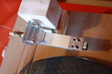
Back to JRKO - I've used 6 mm carbon fiber tube with 6 mm ID bearings. I put heat shrink on the tube and then did a press fit for the bearings. Worked pretty well. I had trouble finding an adhesive that worked with the carbon fiber. Anybody got any ideas? 1/4" wooden dowel sometimes works with 6 mm ID or use 5/16" and shave it down a bit if necessary. 1/4" aluminum tubing with heat shrink does well, too. As you can see in the photos, I've started using off the shelf hardware, in this case threaded posts and nylon flanges, partly because it's fairly precisely made and standardized. The V shape to the flat head machine screws centers and aligns the bearing automatically.
DD - Thanks for the big Cantus picture - it makes the job of figuring dimensions and proportions much easier. That LT has to be the benchmark for all other efforts.
Nanook - Thanks for the info on bearings, especially the tolerances of the different grades. I've had pretty good luck with RC car bearings. Recently, I made a run in jig and put about 30 hours on a couple of them. I chose sketchy ones for the first test and they came out spinning quieter and spun longer. One possible caveat about ABEC1. Sloppy bearings can tilt and allow the arm and carriage to torque instead of translating smoothly across the beam.
JRKO - The answer to all your questions is "it depends." Bill G has given you good starting points in his reply. My tubes are usually about 9." That's partly because I have about 3" between the bearings to help prevent carriage torquing. As far as I know that's about the only critical thing about bearing spacing. Long arms - more than 5" - get heavy and produce more torque. Less than that, 4 - 41/2 seem to work and handle warps well. Shorter arms produce less torque, but can have a hard time with warps. Light weight is good, but again, not too light because weight keeps the bearings tracking right so the carriage moves smoothly. You can test this easily - after you get things assembled, lift the headshell on your finger and move it. If the carriage twists, you need more weight. On the other hand, if the movement is sluggish, you may need to remove weight. See what I mean about "it depends?" I usually wind up between 45 and 60 gr. for the whole works, including cartridge and stylus. 15 mm bearings may be a little heavy, but "depending," they might work fine. Make sure they're completely clean and try running them in if you can. Go ahead and build one, see what happens and what you learn. Please be sure to let us know.
BillG - Congratulations, that's one handsome LT you've produced. Thanks for the photos. You've broken a lot of new ground here. I like your idea of an adjustable tripod base, especially in the prototyping stages. My world is suddenly full of "gottas," - leaky roof, that sort of thing - so there hasn't been much LT progress here.
Back to JRKO - I've used 6 mm carbon fiber tube with 6 mm ID bearings. I put heat shrink on the tube and then did a press fit for the bearings. Worked pretty well. I had trouble finding an adhesive that worked with the carbon fiber. Anybody got any ideas? 1/4" wooden dowel sometimes works with 6 mm ID or use 5/16" and shave it down a bit if necessary. 1/4" aluminum tubing with heat shrink does well, too. As you can see in the photos, I've started using off the shelf hardware, in this case threaded posts and nylon flanges, partly because it's fairly precisely made and standardized. The V shape to the flat head machine screws centers and aligns the bearing automatically.
Attachments

Hi Doug,
Thanks for the compliment. There are other forums that deal with records and music etc., but I think it appropriate to use this thread for a bit on performance of the equipment we are DIYing here. Years ago the company I worked at had an internal forum on the company communications system dealing with AUDIO/hi-fi/DIY much like this forum. Some of the fellows were getting quite sophisticated with their systems and frequently talked about "air" around performers, notably soloists both instrumental and vocal. All my efforts over the years have given a lot of pleasure and some mighty fine sound. The "air" has always eluded me. Maybe I just didn't know what to listen for. The other evening I had a recording of oboe selections playing. The sound stage was excellent for depth and width and all the other good attributes and I was really enjoying it. This recording is one of my favorites. Then it hit me like a ton of bricks. There was "AIR" all around the oboe and the player. He was there on stage with his oboe and there was air all around him. The rest of the players and the room were all there in their appropriate places and nicely delineated but the oboe was there in its spot surrounded by empty air and the sound of it was coming out of that space. WOW! I've listened for this on several other recordings now and it is there too. Without the LT and the careful setup and good cartridge (Signet KT5e) I would never have heard it. The fellow who most often mentioned "air" was using a much worked over TT, and a Signet cartridge as well.
BillG
Thanks for your help and inspiration guys.
I've got pretty much all my materials now.
I really liked the flat'n'fat look of the arm nbocca made. And so I'll be using a home made laminate of 2mmx12mm carbon fibre batten sandwiched between 2 layers of 0.8x25mm carbon fibre batten. Its almost perfectly stiff apart from some slight bend under high pressure which it will never experience in use. Counterweights will be bolts dropped into a slot in the opposite end of the arm.
threaded posts like dtut uses for the simple reason that I can get an easily duplicated exact length.
Last thing to decide on is material & method to join bearings to arm - ply seems the simple and cheap route....
Copper tubing for the tube - options are 22mm or 28mm. The only downside to the larger diameter that I can see, is that the softer interior diameter slope would allow 'slop' in the arm so I'll go with 22mm unless someone says otherwise.
One last question if I may: is there a reason no one has extended the rods connecting the carriage to the bearings and placed counter weights there?
JRKO,
Can you post a link to nbocca's carbon fiber sandwich arm? I'd like to see that.
If you have it or can get it, 3mm mahogany marine ply works very well - very little self or transmitted resonance. Mahogany door skin is a bit thicker and heavier, but also works well.
My experience is that a steeper inside diameter works best.
I believe extending the bearing supports for the CW would lead to unnecessary complication because of the spacing and perhaps problems with disequilibrium if you had to use two CWs.
Good luck and please keep us posted. It's great to see a new LT being built.
Sorry I meant this image of nbocca arm - I like the continuous width arm/headshell for its form, function & simplicity.
I was going to have my tube running low as possible, maybe even behind the platter and just take the arm out of the tube when a record has finished. A simple arm rest on top of the tube support structure to hold the arm when not in use.
How do you feel about cutting the tube down to a 'gutter', like a curved version of the '90deg- angle- glass' solution?
The only thing I need to look into is wiring the cartridge. I read floppy Nokia earbud wire. Any other recommendations/reading?
Attachments
JRKO,
Thanks for posting that picture. That's a very attractive arm. That idea is worth stealing, the highest possible praise.
I'm curious about your arm-removal scheme and what it will look like when you're done.
I've considered a "gutter," especially one with a small diameter and steep sides. I never figured out a satisfactory way to split a tube and I think it will need external support. Again, I'm curious about what you might come up with. No one idea has to be perfect - or even much good at all - but they all deserve at least a bit of experimenting. Which brings me back to an earlier question of yours. Go ahead and try extending the bearing posts to make the CW stub and see how it works. It could have advantages that aren't immediately apparent.
Nokia bud wire works pretty well. Thrift stores have it. Just check through the ones they have for the floppiest one. Use a soldering iron to remove the insulation right around the wires.
Slotted glass tubes may be difficult to source for most people. What about acrylic tubes, or even square acrylic tubes?
difficult to source
That is exactly why I built the glass trak V channel. Cheap, available, easy to do, material can be had at the local hardware store, storm window place etc. They will even cut the nice little strips you need with straight, parallel edges. Then some cyanoacrylate along the mating edges, hold it in place for a few minutes and you have your trak I am very surprised that the idea hasn't produced a flock of copies yet.
BillG
Slotted glass tubes may be difficult to source for most people. What about acrylic tubes, or even square acrylic tubes?
I am very surprised that the idea hasn't produced a flock of copies yet
My immediate thought when you mentioned the V set up was that the bearings might fall into the V and not be able to recover normal movement. I know you have not complained of that happening, but for some reason a tube track seems, to me at least, to allow smoother movement.
The V groove though does appeal with regards to the bearings maintaining a very linear movement whereas the tube allows some degree of 'slop' that can be corrected with smaller dia tube - which is why I need smaller bearings than 15mm
Interesting thoughts
My immediate thought when you mentioned the V set up was that the bearings might fall into the V and not be able to recover normal movement. I know you have not complained of that happening, but for some reason a tube track seems, to me at least, to allow smoother movement.
The V groove though does appeal with regards to the bearings maintaining a very linear movement whereas the tube allows some degree of 'slop' that can be corrected with smaller dia tube - which is why I need smaller bearings than 15mm
some thoughts
Hi JRKO,
I assume you are thinking of the chance that one edge of the bearing outer race or the other edge could get trapped by the junction point of the sides of the V. (upside down apex). I suppose that could happen if you lift the arm too high. In normal use this doesn't happen even when lifting the arm wand enough to change the record. The OD of my bearings is a smidge under 10mm. This places them quite close to the apex. It also makes it necessary to cut a clearance grove in the under side of the bearing support rods so they won't ride on the upper edge of the glass V. Looking closely at the bearing/glass contact points and raising or lowering the arm wand shows very little travel of that contact point up or down the side of the V. So in my case that problem doesn't exist.
If your preference is for a shallower V, it is very easy to select the desired angle with a gluing fixture with a different angle. I made two brass shim stock pieces and glued them to the outside surface of the glass slips with the slip edges in contact. When the glue dried, it was easy to bend them to the desired angle and apply the bonding agent to the glass. Very shallow angles could be gotten this way.
My arm as pictured uses the 90 degree V. An expedient of having one all made up. One of the pictures on this thread shows bearings which are somewhat more than twice the thickness of my bearings. This easily raises the depth of the bearing into the V and should minimize if not eliminate the need for undercutting the support rods. I think I will look into this.
The normal radial play of the inner race in the outer race easily compensates for the little wows you get from a slightly warped record. The bearing should not ride up the V walls. For gross wows I think the sharper V angle should provide better recovery of operating position and greater stability of the arm when manually moving it from one end of the track to the other. It won't tend to jump of the track.
Keep in touch. Looks like you will produce something that will work well. Good Luck!
BillG
My immediate thought when you mentioned the V set up was that the bearings might fall into the V and not be able to recover normal movement. I know you have not complained of that happening, but for some reason a tube track seems, to me at least, to allow smoother movement.
The V groove though does appeal with regards to the bearings maintaining a very linear movement whereas the tube allows some degree of 'slop' that can be corrected with smaller dia tube - which is why I need smaller bearings than 15mm
Hi JRKO,
I assume you are thinking of the chance that one edge of the bearing outer race or the other edge could get trapped by the junction point of the sides of the V. (upside down apex). I suppose that could happen if you lift the arm too high. In normal use this doesn't happen even when lifting the arm wand enough to change the record. The OD of my bearings is a smidge under 10mm. This places them quite close to the apex. It also makes it necessary to cut a clearance grove in the under side of the bearing support rods so they won't ride on the upper edge of the glass V. Looking closely at the bearing/glass contact points and raising or lowering the arm wand shows very little travel of that contact point up or down the side of the V. So in my case that problem doesn't exist.
If your preference is for a shallower V, it is very easy to select the desired angle with a gluing fixture with a different angle. I made two brass shim stock pieces and glued them to the outside surface of the glass slips with the slip edges in contact. When the glue dried, it was easy to bend them to the desired angle and apply the bonding agent to the glass. Very shallow angles could be gotten this way.
My arm as pictured uses the 90 degree V. An expedient of having one all made up. One of the pictures on this thread shows bearings which are somewhat more than twice the thickness of my bearings. This easily raises the depth of the bearing into the V and should minimize if not eliminate the need for undercutting the support rods. I think I will look into this.
The normal radial play of the inner race in the outer race easily compensates for the little wows you get from a slightly warped record. The bearing should not ride up the V walls. For gross wows I think the sharper V angle should provide better recovery of operating position and greater stability of the arm when manually moving it from one end of the track to the other. It won't tend to jump of the track.
Keep in touch. Looks like you will produce something that will work well. Good Luck!
BillG
Thanks for your thoughts/experiences BillG
I'm gonna try the tube first, then a glass V and then a shallow gutter which is the sort of halfway house. Interchanging them shouldn't be too hard.
I like the idea that I can have multiple arms that are so easily built - so many options 😀
I'm gonna try the tube first, then a glass V and then a shallow gutter which is the sort of halfway house. Interchanging them shouldn't be too hard.
I like the idea that I can have multiple arms that are so easily built - so many options 😀
Quote: Slotted glass tubes may be difficult to source for most people. What about acrylic tubes, or even square acrylic tubes?
While it is possible to use a wide variety of materials for the main tube or track the reason why glass was chosen is for its hardness. Friction is important to minimize in a design such as this and the harder the track the lower the friction, any plastic will result in much more friction when compared to a glass track. This is one of those situations where the harder the materials used the better. I suppose that Ceramic bearings and a tungsten tube would be about as hard as you are going to easily get. Harder materials are available but not easily or reasonably. Best regards Moray James.
While it is possible to use a wide variety of materials for the main tube or track the reason why glass was chosen is for its hardness. Friction is important to minimize in a design such as this and the harder the track the lower the friction, any plastic will result in much more friction when compared to a glass track. This is one of those situations where the harder the materials used the better. I suppose that Ceramic bearings and a tungsten tube would be about as hard as you are going to easily get. Harder materials are available but not easily or reasonably. Best regards Moray James.
Thanks for that Moray James - I need to pose some questions so I can better grasp the fundamentals.
I understand that the surface of say, copper is more easily damaged, and so softer than glass and I think(?) that and acrylic tube would be harder than the copper.
1)What would be the difference in sound in this application? The whole carriage weighs very little and the total contact/friction area between bearing and tube must be a single square millimetre or so.
2)Isn't bearing choice a greater issue as they have the major contact/friction area internally and so the change to ceramic outweigh the benefit of a change of tube from copper to glass?
3)Would't a harder material like glass be more susceptible to ringing from the music than a softer material? Could that be an issue of the tube passing vibration back to the arm assembly?
4)If you minimise contact friction between bearing and tube too much wont the bearing simply be dragged along the tube and be worse than a softer material anyway?
Thanks in advance for bearing (pun intended) with me!
Re: materials for track
the copper tube you can easily get comes in 2 forms, the hard drawn tube you would use for the track has good interior finish, uniform dimensions and round. It is not highly susceptible to damage and will resist deformation well for a long time. But its coefficient off friction is certainly higher than glass. The other copper tube is annealed copper. You buy it in large coils and straighten it out manually and bent it around obstacles. Nuff said, you don't want it. Drawn aluminum is another candidate. If anodized after polishing the surface is quite hard. I expect that its coefficient of friction is higher than copper. Stainless steel is another candidate, but it is difficult to work, perhaps more so than glass.
Let's look at where the bearing hits the wall. Something round against something flat and where do they meet? At a point if I remember correctly. Point contact, you can't get much smaller than that. All the pressure is concentrated at that point. Now that is where you want the mating surfaces to be the hardest. If anything is going to deform it will do so there,
I think the acrylic tube will eventually exhibit the track the bearing rolls in as it goes across the records. The plastics have cold flow and will conform to the shape of the mating part. The point contact is lost, friction goes up, the bearing gets stuck in the track, etc.
In the case of glass, none of this foul stuff takes place. Friction is much lower. You don't have to deal with cold flow. Point contact remains. BTW if you reduce the coefficient to zero it matters not if you drag the bearing along. You don't need it.
Regarding the bearing's internal friction, I think that point contact between the balls and the races is applicable here also. The actual position of the points will be a function of the direction of the bearings loading. Not done a rigorous analysis of this one. Yes I do think that ceramic bearings could give a benefit here. I want to try some full ceramic silicon nitride bearings soon.
Regarding ringing of the glass track, I've not given it any thought till just now. For my arm I have never seen an arm with less sonic problems such as ringing. Hang a glass tube up from a point( a hole) close to the end of the tube and tap it. We have one note of the wind chime, pure and sustained. Grab it with a harness of any kind at the same position, ringing gone. The glass tube track needs to be mounted at one end in some kind of structure. Ringing is damped. The softer the mounting the greater the damping. Put something at the far end of the tube to keep the carriage from running of the track and you have more damping. Use flat glass side walls making a V. You have to mount it by one end and put a barrier at the far end. You have damped it. Form the V by gluing the 2 sides at the apex with cyanoacrylate glue and you have structural damping plus the damping provided by the adhesive. Almost forgot, you have the pressure points of the bearings coupled to the glass some 2 or more inches part along the track. I think that there is very little chance of the track ringing.
Difference in sound?? Have nothing to indicate what differences in sound as a function of materials used for the structure will be. Perhaps after enough of us have built enough arms of different designs and materials we will have some idea. I think it will be highly subjective. In the ear of the listener.
Great to think these issues through, and I could be way off base on smoe of them.
BillG
Thanks for that Moray James - I need to pose some questions so I can better grasp the fundamentals.
I understand that the surface of say, copper is more easily damaged, and so softer than glass and I think(?) that and acrylic tube would be harder than the copper.
1)What would be the difference in sound in this application? The whole carriage weighs very little and the total contact/friction area between bearing and tube must be a single square millimetre or so.
2)Isn't bearing choice a greater issue as they have the major contact/friction area internally and so the change to ceramic outweigh the benefit of a change of tube from copper to glass?
3)Would't a harder material like glass be more susceptible to ringing from the music than a softer material? Could that be an issue of the tube passing vibration back to the arm assembly?
4)If you minimise contact friction between bearing and tube too much wont the bearing simply be dragged along the tube and be worse than a softer material anyway?
Thanks in advance for bearing (pun intended) with me!
- Home
- Source & Line
- Analogue Source
- Opus 3 Cantus parallel tracking arm