Thanks for that Moray James - I need to pose some questions so I can better grasp the fundamentals.
I understand that the surface of say, copper is more easily damaged, and so softer than glass and I think(?) that and acrylic tube would be harder than the copper.
1)What would be the difference in sound in this application? The whole carriage weighs very little and the total contact/friction area between bearing and tube must be a single square millimetre or so.
2)Isn't bearing choice a greater issue as they have the major contact/friction area internally and so the change to ceramic outweigh the benefit of a change of tube from copper to glass?
3)Would't a harder material like glass be more susceptible to ringing from the music than a softer material? Could that be an issue of the tube passing vibration back to the arm assembly?
4)If you minimise contact friction between bearing and tube too much wont the bearing simply be dragged along the tube and be worse than a softer material anyway?
Thanks in advance for bearing (pun intended) with me!
1) different materials will have different sonic qualities. You will have to experiment and see for yourself. In this application bearings which are intended for ultra low friction would be my first choice though I would also be temped to experiment with bearings which are intended for ultra low noise as well.
2) Generally when you design parts that move you design one part to be sorter so that part will wear first. This part is generally the less expensive or the easier part to get to to replace. I think that using a glass tube with a mohs hardness of about 6 and a bearing with a harder material makes thee most sense. I am not sure that I understand your question so if I have missed the point please reword it for me.
3) If you mount your glass tube into a material of similar hardness you can divert the energy some and then deal with it. A layer of shrink tube on the glass will damp it significantly especially if the shrink tube is adhesive lined. It does not always take a lot to damp things at high frequencies. You might have success with a few layers of clear lacquer on the outside of the tube. I see this as a design tweak rather than a major issue as bare glass works extremely well.
4) If you could reduce the drag or friction to zero sure the sled would just be dragged along and that would be fine. I think that some attention to sled geometry with respect to bearing contact and the sleds ability to track in a straight line would be beneficial. When the arm rides a warp the sled is literally dragged up the wall of the tube and gravity pulls it back down for you this is where riding the inside of a tube is so much better than riding on the outside of a tube. Inside gravity works for you and outside it just helps you to fall off. This design of Bo's is so clever and so very simple so very well thought out.
I hope this helps and is of some use. Best regards Moray James.
Haha! what a dumb question my no.4 was - if its frictionless its nirvana, not a problem!!!
Right - Nuf talky - more buildy!
Right - Nuf talky - more buildy!
purchases
Hi everyone,
I learned from this thread about the passing of Bo Hansson, very sorry about this. Does anyone here know whether his company is still selling his Cantus tonearm or parts for it? I've emailed to the address on his website, but my message as returned to me as undeliverable.
Thanks for any news,
Sean
that's the plan...
Well, I'm gathering parts to do exactly that. Thought about buying the support block part, though. Trying to figure out having decent VTA adjustment, my solutions aren't so elegant yet...
cheers
see if you can find a reseller maybe.
Or build you own 😀😀
Well, I'm gathering parts to do exactly that. Thought about buying the support block part, though. Trying to figure out having decent VTA adjustment, my solutions aren't so elegant yet...
cheers
off the top of my head the only VTA built in on the DIY versions I can remember is to mount the tube 'block' on a large threaded bar.
how about allowing the block to slide up a delrin rod and shim it out as needed?
I'm just going to set mine within my cartridges ideal a be done. Guess it depends o the compliance but thats been discussed a few pages back.
how about allowing the block to slide up a delrin rod and shim it out as needed?
I'm just going to set mine within my cartridges ideal a be done. Guess it depends o the compliance but thats been discussed a few pages back.
Just checking in
Hi gang,
Just checking in to let you all know I'm still here. Been busy around the house and there were a few clocks to tend to. So nothing much with the Cantus Clone save listening to some music with supper or other odd moments. I'm still very pleased with the LT arm and a polished design is shaping up in my mind. Got to find some good wire soon and come up with a good support for it so that there is no, or at least uniform, drag on the carriage. What I'm using now occasionally causes skips. Most of the time though, no problem. I'm anxious to see some more results on these projects.
BillG
off the top of my head the only VTA built in on the DIY versions I can remember is to mount the tube 'block' on a large threaded bar.
how about allowing the block to slide up a delrin rod and shim it out as needed?
I'm just going to set mine within my cartridges ideal a be done. Guess it depends o the compliance but thats been discussed a few pages back.
Haha! what a dumb question my no.4 was - if its frictionless its nirvana, not a problem!!!
Right - Nuf talky - more buildy!
Hi gang,
Just checking in to let you all know I'm still here. Been busy around the house and there were a few clocks to tend to. So nothing much with the Cantus Clone save listening to some music with supper or other odd moments. I'm still very pleased with the LT arm and a polished design is shaping up in my mind. Got to find some good wire soon and come up with a good support for it so that there is no, or at least uniform, drag on the carriage. What I'm using now occasionally causes skips. Most of the time though, no problem. I'm anxious to see some more results on these projects.
BillG
Last edited:
VTA,
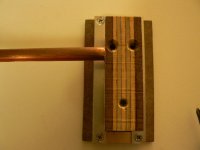
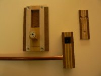
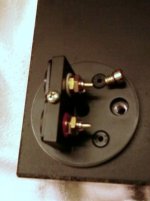
The screw head is captured between the t-nut and the cap. Screwing it in lowers the arm, screwing it out raises it. I thought the pictures would do a better job of showing how things work. If there are questions, I'll be glad to help.
The screw head is captured between the t-nut and the cap. Screwing it in lowers the arm, screwing it out raises it. I thought the pictures would do a better job of showing how things work. If there are questions, I'll be glad to help.
Attachments

Hello everyone, 🙂 I take this post in progress and will try to make my small contribution.
Here is an arm that I made inspired by the design of "cantus", except that the arm is pneumatic, decoupling and damping of the arm support is provided by a viscous liquid ..😉
Here is an arm that I made inspired by the design of "cantus", except that the arm is pneumatic, decoupling and damping of the arm support is provided by a viscous liquid ..😉
Attachments
Brilliant!
Thanks for sharing your system, that's a terrific solution. My version is leaning a bit heavier in terms of materials, and it's nice to see how simply it can work.
Are the other two screws in the top plate holding/leveling the copper tube? I was trying to figure out how to accomplish leveling the tube, the mounting plate and VTA altogether, seems like your version manages it nicely.
Thanks!
VTA,
The screw head is captured between the t-nut and the cap. Screwing it in lowers the arm, screwing it out raises it. I thought the pictures would do a better job of showing how things work. If there are questions, I'll be glad to help.
Thanks for sharing your system, that's a terrific solution. My version is leaning a bit heavier in terms of materials, and it's nice to see how simply it can work.
Are the other two screws in the top plate holding/leveling the copper tube? I was trying to figure out how to accomplish leveling the tube, the mounting plate and VTA altogether, seems like your version manages it nicely.
Thanks!
MWC,
Yes, the arm tube rides on a small ridge inside the hole in the support block. The screws secure it and act as leveling adjusters.
Sourdingue,
That's beautiful work - on both arms.
"decoupling and damping of the arm support is provided by a viscous liquid" I'd like to know more about that
Yes, the arm tube rides on a small ridge inside the hole in the support block. The screws secure it and act as leveling adjusters.
Sourdingue,
That's beautiful work - on both arms.
"decoupling and damping of the arm support is provided by a viscous liquid" I'd like to know more about that
hello "dtut"🙂 in fact the arm support is hollow and filled with a liquid of high viscosity, 90% of the contact surface between the base of the plate and support arms are "liquid" .. a small picture certainly tell you more ...🙂
Attachments


Originally Posted by JRKO View Post
off the top of my head the only VTA built in on the DIY versions I can remember is to mount the tube 'block' on a large threaded bar.
DTUT & others,
I have been looking carefully at pics of OPUS 3 CANTUS and am not seeing provision for VTA or leveling. The RAUNA supplied mounting instructions say to glue the arm to the plinth after establishing the correct position. Can any of you dear readers comment on what OPUS 3 expects the user to do. References in this forum mention using a slight down angle for the tube and BO's comments say he keeps the tube level. This appears to me to be the only area not sufficiently defined for the original O3C and I am real curious about it.
BillG
VTA
Pardon me for being so dense on this one. I can't find any pics of the completed arm to show what the assembly shown by those 3 pics is actually doing, and looking at the 3 pics is still drawing a blank. Doug, would you please complete the picture for me. It is clear how the screw and t-nut can be an adjustable stop, but how the rest of the parts function and go together is still a mystery.
BillG
VTA,
The screw head is captured between the t-nut and the cap. Screwing it in lowers the arm, screwing it out raises it. I thought the pictures would do a better job of showing how things work. If there are questions, I'll be glad to help.
Pardon me for being so dense on this one. I can't find any pics of the completed arm to show what the assembly shown by those 3 pics is actually doing, and looking at the 3 pics is still drawing a blank. Doug, would you please complete the picture for me. It is clear how the screw and t-nut can be an adjustable stop, but how the rest of the parts function and go together is still a mystery.
BillG
I gather from the photos and description that the copper arm tube is resting on a ridge point inside the block, like a seesaw, and the two screws are acting to balance the tube on either side of it. Pressure from the screws balance the arm tube as well as hold it in place.
Looking at the original Cantus, it does not seem to have integrated VTA adjustment or tube-leveling adjustment like Dtut's design.
I'm trying out my own version, along these lines, to have arm-leveling and VTA adjustability within the mounting block. As soon as I can carve out some workshop time (hopefully this weekend), I'll post some pictures of progress. I'm very excited about this arm design and the simplicity is very encouraging.
cheers
Thanks MWC. Your description clicked instantly. It is beyond me why I didn't see it right off. I think I will sketch it out to see just how to apply the idea to my arm with the glass V track. It should be easy enough to mount the V track in a short cylindrical holder which goes into a mating hole with the ridge. This holder then goes directly into the mounting block (or something like that).I gather from the photos and description that the copper arm tube is resting on a ridge point inside the block, like a seesaw, and the two screws are acting to balance the tube on either side of it. Pressure from the screws balance the arm tube as well as hold it in place.
Looking at the original Cantus, it does not seem to have integrated VTA adjustment or tube-leveling adjustment like Dtut's design.
I'm trying out my own version, along these lines, to have arm-leveling and VTA adjustability within the mounting block. As soon as I can carve out some workshop time (hopefully this weekend), I'll post some pictures of progress. I'm very excited about this arm design and the simplicity is very encouraging.
cheers
BillG
This may be gilding the lily or a solution in search of a problem - great quote about Vincent motorcycles in another thread - but it does seem to work.
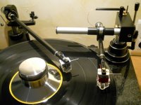
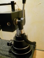
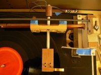
I've been playing with this magnetic guide for a couple of months. The idea is to take a bit of weight off the bearings while still making sure the carriage stays aligned in the tube. Normally, a certain minimum weight is necessary to keep the bearings in the bottom of the tube so the carriage doesn't chatter or torque. With the mag guide, the arm/carriage can be lighter because the magnetic field provides the alignment so the stylus has less mass to move. This arm/carriage combo, including CW, cart and stylus, comes in at just under 60 gr and could be less. The mag guide might make it possible to use a considerably longer arm wand, but I haven't explored that yet.
There are small neodymium magnets under the blue tape. The bar is tool steel. The magnets seem to react differently to round and square bars, but I haven't figured out which is best.
The arm works without the mag guide, but the carriage lurches and the stylus is constantly hunting. With the mag guide, the translation is smooth and the stylus stays centered - and as an added, unexpected bonus, the mag guide damps the vertical motion on warps. I have an Emmy Lou Harris record which is both eccentric and warped and they coincide - a nasty ride for any arm. The mag guide arm handled it very well.
To set it up, the CW moved to the end of its stub and the arm is zeroed by moving the mag guide. Then the CW is moved forward to set the VTF. It's a bit like the dynamic adjustment on an Ortofon or Empire. The arm tracked just fine at 1.5 gr on a much abused Shure M91ED.
Now to get some glass cut and see how well this works with BillG's design.
Attachments

mag guide
Doug, that is a stroke of genius! I'll be trying it out soon, very soon.
DTUT wrote:
"The arm works without the mag guide, but the carriage lurches and the stylus is constantly hunting. With the mag guide, the translation is smooth and the stylus stays centered - and as an added, unexpected bonus, the mag guide damps the vertical motion on warps."/end quote
Your lurches and hunting suggests that the bearings you are using on this model along with the condition of the tube are far from optimum (poor?). That the mag guide effectively compensates for whatever is ailing that setup is amazing. That you have achieved 1.5 gram tracking is another great achievement. I'm thinking that partially unloading the bearings, as you have done, also permits you to more accurately measure the tracking force. This has always been a problem for me even though I have a pretty good setup now. I really would like to improve that parameter. Simply using a lighter carriage doesn't seem to be the answer. We need to get a more complete analysis of the new "system".
Keep at it!
BillG
This may be gilding the lily or a solution in search of a problem - great quote about Vincent motorcycles in another thread - but it does seem to work.
I've been playing with this magnetic guide for a couple of months. The idea is to take a bit of weight off the bearings while still making sure the carriage stays aligned in the tube. Normally, a certain minimum weight is necessary to keep the bearings in the bottom of the tube so the carriage doesn't chatter or torque. With the mag guide, the arm/carriage can be lighter because the magnetic field provides the alignment so the stylus has less mass to move. This arm/carriage combo, including CW, cart and stylus, comes in at just under 60 gr and could be less. The mag guide might make it possible to use a considerably longer arm wand, but I haven't explored that yet.
There are small neodymium magnets under the blue tape. The bar is tool steel. The magnets seem to react differently to round and square bars, but I haven't figured out which is best.
The arm works without the mag guide, but the carriage lurches and the stylus is constantly hunting. With the mag guide, the translation is smooth and the stylus stays centered - and as an added, unexpected bonus, the mag guide damps the vertical motion on warps. I have an Emmy Lou Harris record which is both eccentric and warped and they coincide - a nasty ride for any arm. The mag guide arm handled it very well.
To set it up, the CW moved to the end of its stub and the arm is zeroed by moving the mag guide. Then the CW is moved forward to set the VTF. It's a bit like the dynamic adjustment on an Ortofon or Empire. The arm tracked just fine at 1.5 gr on a much abused Shure M91ED.
Now to get some glass cut and see how well this works with BillG's design.
What a brilliant concept. The magnets will lighten the carriage weight on the bearings and also provide damping similar to the suspended string arm with magnetic damping.
Wayne - Yes, that was the plan. It's all Frank Schroeder's fault.
BillG - The mag guide was added to a project I'd been working on for a while. The tube interior is polished smooth and the bearings spin freely, but it still wasn't working well. I think it has something to do with the ratio of bearing size to tube diameter and what part of the bearing corner hits the tube wall and where - in other words, the contact amount and angle. It seemed to me that using a sketchy project might demonstrate the advantage, if any, of the mag guide more clearly. If it went from not OK to OK, then the difference had to be the guide. Subtle can come later.
I'm going to test the weight hypothesis by building an arm as close to 45 gr as I can. Normally, that size arm would be out of control. I'd like to test the guide with a longer wand, too. And then there's shielding to focus the mag field. This is going to keep me busy for a while.
A local shop is cutting the glass I need to try your trough design.
- Home
- Source & Line
- Analogue Source
- Opus 3 Cantus parallel tracking arm