.................. I preferred to take +/-25V DC in order to live a little in the "safe" side.
The gain I'm using is about 27 dB, which gives a 1V sensibility for full output at +/-25V DC.
That does not compute.
A gain of +27dB equates to 22.39times.Why not??? 😕 😕
Can you get 22.39 times 1Vac out of the chipamp running on ±25Vdc supplies?
BTW, 22.39*1Vac = 31.66Vpk
Last edited:
I'm talking about a supply +/-25V, so... yes, I can get +/-22.93V peak at the output if I give it 1V peak at the input as I said.A gain of +27dB equates to 22.39times.
Can you get 22.39 times 1Vac out of the chipamp running on ±25Vdc supplies?
BTW, 22.39*1Vac = 31.66Vpk
I'm not talking about RMS values...
The gain I'm using is about 27 dB, which gives a 1V sensibility for full output at +/-25V DC.
now you have changed to Vpk whereas you posted V earlier.I'm talking about a supply +/-25V, so... yes, I can get +/-22.93V peak at the output if I give it 1V peak at the input as I said.
I'm not talking about RMS values...
So I will ask the question:
will a 7294 running on a quiescent supply of ±25Vdc, deliver 22.39Vpk into your test load of 4r0?
A severely distorted test signal.Gosh just measure the output and see What's behind door #1 with 1 volt input...
+-25vdc and 27x could make sense, if the board layout was also pretty good.
If the layout wasn't quite as good as that, the amp (at that voltage) would need the gain set about 29x for running cool and stable, while also driving a real speaker.
Other tips:
Replace feedback-shunt (not the feedback resistor, but rather its partner) with a multi-turn trimmer to fine tune and discover the right gain factor, for the purposes of promoting good stability, not only on the workbench, but also while running a real speaker.
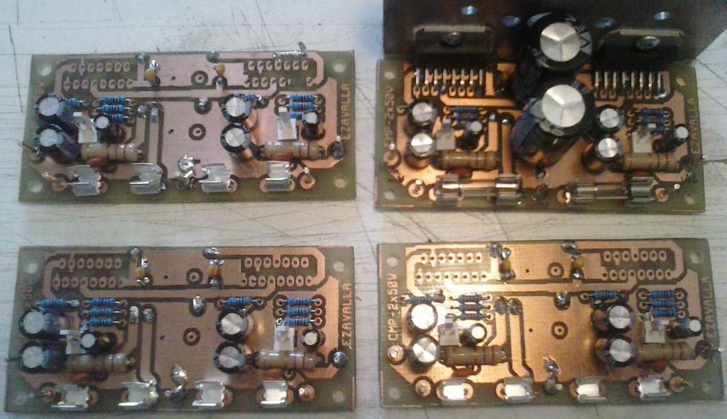
Big caps go on the power board, smaller caps go on the amp board--the power circuit (cap values) shown in the TDA7294 schematic will cause overheat.
If the layout wasn't quite as good as that, the amp (at that voltage) would need the gain set about 29x for running cool and stable, while also driving a real speaker.
More than anything, the higher voltage and loading had hindered the stability enough to cause the temp to go up a lot. If at +-31vdc try TDA7294 with the gain set in the range of 35x to 37x. Note, at that voltage, if you had wanted success with the gain lower than that, use the TDA7293 chip for it.I've tested the amplifiers with +/-31V DC on a 4 ohms load and they run pretty well, but the temperature starts to increase very fast....
Other tips:
Replace feedback-shunt (not the feedback resistor, but rather its partner) with a multi-turn trimmer to fine tune and discover the right gain factor, for the purposes of promoting good stability, not only on the workbench, but also while running a real speaker.
Big caps go on the power board, smaller caps go on the amp board--the power circuit (cap values) shown in the TDA7294 schematic will cause overheat.
I haven't changed anything, I've just added the "peak" word to make clear my previous calculation which should be clear from the context.now you have changed to Vpk whereas you posted V earlier.
OK, it doesn't matter now. It's clear anyway 😉
No.. not really... it delivered about 21.5V peak, but you know they are due to the higher load on the power supply and the internal losses of the chip.So I will ask the question:
will a 7294 running on a quiescent supply of ±25Vdc, deliver 22.39Vpk into your test load of 4r0?
I have to say that it was a VERY short term test because it isn't a real operation condition and I hadn't got the right heatsinks yet 😱. The test was run more as a proof of "fake-or-not" device.
Even when it was a short test, there wasn't any inestability in the output signal. Not a visible one in the scope screen, neither in the FFT mode. As the datasheet says (and I believe 😉) this chip should be stable with a closed loop gain of at least 24dB, and using 27dB the nine chips I tested where stable in those tests. I know I should repeat the tests using an square wave, but I've got the heatsinks just a couple of weeks ago and I haven't got enough time to mount them..More than anything, the higher voltage and loading had hindered the stability enough to cause the temp to go up a lot. If at +-31vdc try TDA7294 with the gain set in the range of 35x to 37x. Note, at that voltage, if you had wanted success with the gain lower than that, use the TDA7293 chip for it.
What is the value of the two biggest caps?
What are the values of all of the power decoupling caps?
What are the values of all of the power decoupling caps?
You could try 220uF 50v caps (under board) parallel to those 2200uF caps, and, also, one (just 1) 2.2uF 250v cap from V+ to V- at the dc cable hookup point, and see if the amp runs better, with hopefully, less heat when you try +-31vdc.The value of the caps is as per datasheet: 2200uF + 0.22uF.
Both caps are decoupling ones.
That method is outdated, but it will fit and probably work. I sometimes use it for refit on production amplifiers.
Last edited:
I guess it's better to add a couple of 100nF (under board) just between +V/-V and GND very near the chip leads. But I haven't instruments to measure any effect they can produce, so... I'll keep the current configuration while the amplifier is stable.
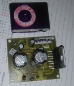
Here's the kits that I've bought a year ago (lol) didn't had a goood preamp back than and didn't used them.
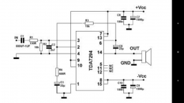
Why is r3 to pin 6 and than to output ( trough the bootstrap cap) not directly r3 on output?.
Even on the datasheet schematic r3 is on pin 14
On my board it is on pin 6
Why is r3 to pin 6 and than to output ( trough the bootstrap cap) not directly r3 on output?.
Even on the datasheet schematic r3 is on pin 14
On my board it is on pin 6
Attachments
On that design, I think it is surely necessary that the power source voltage and current, be kept very far smaller than the amplifier's rated capacity.
Hi,
Someone tried to use a gain less than 24db?
I used a gain of 2.0 without problems. Its perfect.
Now I need to use a gain of 2.9 and I am experiencing problems.
I have peak voltage of 12V from a preamplifier stage and I want to have 35V at the output.
The problem I have is that the TDA gets hot, even without load and without signal.
I am using:
+40V -40V
R1=33K
R3=33K
R2=17.2K
C2=22u
C5=22u
R6=2.7R
C10=100nF
Is this an unstable configuration? why?
This issue has been fixed by removing the Boucherot cell. But I must emphasize that you can use the circuit with less gain than 24dB.
I have always used it with low gain values and good performance.🙂
I have always used it with low gain values and good performance.🙂
This issue has been fixed by removing the Boucherot cell. But I must emphasize that you can use the circuit with less gain than 24dB.
I have always used it with low gain values and good performance.🙂
There is production variance and also fakes available.
The input current permissible for stability (affects heat) depends on the input transistor qualities. The 3 probable variants include old production TDA7294 (much like current production TDA7293), fake and new production TDA7294 (much like TDA7296).
Too much heat, or anything less than 70% efficiency does happen to indicate a linearity error. Adjusting the component values and voltage will cure the error temporarily, until you purchase another almost random (internally) chip.
As of this time, the scale of the current market TDA7294 range from table radio amp to small venue concert amp and you'll need a fully functional crystal ball or an awful lot of labor to figure the difference. It will be more convenient to purchase the TDA7293 instead. Even though the pinout of the TDA7293 is madder (even worse), the variety is much smaller and more convenient, since the range of variance is from 45W to 75W, rather than the TDA7294's variants range of 8W to 70W. The current matters are rather important for linear amplifiers, so that's why it is important to buy a part that has less variance.
Well, if you've use a TDA7294 really hot and also expected output power, then your power has gone into your heatsink, not your speaker and the design goals have failed. Aiming for lowest gain in that case, reduces stability and makes the matter get ever so much worse. . . because that will just put even more power into the heatsink and even less power into the speaker. The real problem with that is that it sounds really bad when used that way.
The thing is that if you've bought a newly produced TDA7294, then, you need to use the TDA7296 datasheet for it.
- Home
- Amplifiers
- Chip Amps
- Optimizing TDA7294 Output