TDA7294 Stereo board Pin issue
Hi,
I have bought a stereo board for TDA7294 with PSU and speaker protection all on the PCB. Sounded like a good starting point for building a first amplifier.
Probably not regarded the top choice here but I have some Motivation to finish it since I have it here now.
With the plentiful Information very kindly provided in this topic and the (kind of) corresponding TDA7293 topic I have tried to reconstruct the circuit.
One thing I have missed initially was that the bootstrap cap is connected to pin12 on this board instead of pin14. I have measured resistance between pin12 and pin14 of the TDA7294 provided and they seem not to be connected. So likely no fake TDA7293 with TDA7294 Label!?
Labeling says TDA7294 V6.
Well, to make a long story short: can I clip of pin12 and place a jumper to connect the bootstrap cap to pin14?
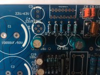
Unfortunately I haven't made a Picture before I started soldering but hopefully the attached one helps (some Details on my understanding of the circuit below). With NFB, bootstrap and power supply bypass provided as 22uF I haven't finished the board but ordered 220uF/63V (NFB, Bypass) and 47uF for bootstrap.
Help would be appreciated! I could also get more Pictures if this is of any help.
Thanks,
Dirk
To the best of my Knowledge:
C3=C8 in datasheed=power supply Bypass
C4=bootstrap cap
C6=NFB cap
C5/C7=mute caps
R1=Feedback resistor
R2=Input load
R3=Feedback shunt
R4=Standbye
R5=Mute
PS: Apologies for my stupid autocorrection capitalizing words all the time...
Hi,
I have bought a stereo board for TDA7294 with PSU and speaker protection all on the PCB. Sounded like a good starting point for building a first amplifier.
Probably not regarded the top choice here but I have some Motivation to finish it since I have it here now.
With the plentiful Information very kindly provided in this topic and the (kind of) corresponding TDA7293 topic I have tried to reconstruct the circuit.
One thing I have missed initially was that the bootstrap cap is connected to pin12 on this board instead of pin14. I have measured resistance between pin12 and pin14 of the TDA7294 provided and they seem not to be connected. So likely no fake TDA7293 with TDA7294 Label!?
Labeling says TDA7294 V6.
Well, to make a long story short: can I clip of pin12 and place a jumper to connect the bootstrap cap to pin14?
Unfortunately I haven't made a Picture before I started soldering but hopefully the attached one helps (some Details on my understanding of the circuit below). With NFB, bootstrap and power supply bypass provided as 22uF I haven't finished the board but ordered 220uF/63V (NFB, Bypass) and 47uF for bootstrap.
Help would be appreciated! I could also get more Pictures if this is of any help.
Thanks,
Dirk
To the best of my Knowledge:
C3=C8 in datasheed=power supply Bypass
C4=bootstrap cap
C6=NFB cap
C5/C7=mute caps
R1=Feedback resistor
R2=Input load
R3=Feedback shunt
R4=Standbye
R5=Mute
PS: Apologies for my stupid autocorrection capitalizing words all the time...
Attachments
Last edited:
solved, it's about the different options for C4
Hi,
by now I have made it. The connection of the bootstrap (pic in post above =C4) can be made via the different positions of C4. Yet, the track is kind of hidden, at least for someone as new to it as me.
Still worth considering to clip Pin12 of the TDA7294 and make connection to Pin14 with a jumper there...if this would work out?
On that version of TDA7294, you can clip Pin12.Well, to make a long story short: can I clip of pin12 and place a jumper to connect the bootstrap cap to pin14?
See TDA7294 datasheet: http://www.st.com/content/ccc/resou...df/jcr:content/translations/en.CD00000017.pdf
For current production TDA7294 (both real and fakes), use TDA7296 datasheet: http://www.st.com/content/ccc/resou...df/jcr:content/translations/en.CD00000198.pdf
Same news, except for lower voltage. Pin 12 is still "N.C." which means you can cut it off if you need to.
Last edited:
hi to all
this topic is too usefull to me and special thanks to diy mans 🙂
last year i have a problem with 7294! mid and hi got noisy :| solved by mute: 10K 30K+4007 and 10uf. stupid problem and solution 😀
this topic is too usefull to me and special thanks to diy mans 🙂
last year i have a problem with 7294! mid and hi got noisy :| solved by mute: 10K 30K+4007 and 10uf. stupid problem and solution 😀
STK Hack
Picked up a Sony HCD BX3/DX3 at the flea market here, for 120 Rupees (about $2).
Display on, no output, most likely the STK 402-100 is blown, and that is unobtanium, as some people say.
I am thinking of putting twin TDA 7293 chips, provided there is room, the heat sink has a fan!
The service manual says +45.5 and -46.4 volts on the STK, which pretty much limits my choices of chips.
I think the TDAs are more reliable than the STKs.
I recently purchased several Philips Powerhouse boxes, turned out to be Matsushita AN7161 power amps, and almost totally Rubycon and Elna caps...for a max. $3, in working condition.
A wash with soapy water, rinse with plain water, open, blow off the dust, spray the pots, check DC offset, and good to go...
I have run some of these with my computers playing MP3s, I need basically amps...can't get much cheaper!
Powerhouse was a series of boxes, dual cassette, tuner, equalizer, mechanical switch for selector... Later versions had a microprocessor for selection.
Last edited:
One older Powerhouse had NEC uPC 1238 with one changed to TDA 2030A
Had to change both due to high DC output, put a TDA 2030A on one channel and a LM 1875 on the other, problem solved.
Odd thing was the speaker was through a capacitor, should not have let DC through.
Now 20 - 30 mV DC, 2 volts without speaker, enough I think to stop fussing.
Had to change both due to high DC output, put a TDA 2030A on one channel and a LM 1875 on the other, problem solved.
Odd thing was the speaker was through a capacitor, should not have let DC through.
Now 20 - 30 mV DC, 2 volts without speaker, enough I think to stop fussing.
Odd thing was the speaker was through a capacitor, should not have let DC through.
If an electrolytic is reverse biased it can let DC pass through it.
After about reverse bias of 1.5 volts it becomes a short.
I changed only the chips, the TDA2030 was reading 17 V DC, the uPC 1238 about 4 V DC
The readings came back to below 50 mV DC after replacing the chip amps, I did not change the electrolytics.
All in all it cost about 400 rupees, a fiver in the UK.
Now I have to build a phono pre amp for it, the new owner, a friend, wants to run his Garrard turn table through it.
Planning a 4558 dual op amp at 14 volts available inside the box, boosting the aux input to feed the existing pre amp inside, again a 4558 or 4560.
His son plugged his 70s Sony amp to 220 volts, it had come with him when he moved from the USA, rated at 110 volts. Died.
Says has a nice red wood cabinet, he will let me see after it has been dug out of a closet...Have to see if it can be made to work. Though if it has those special FETs. ....unobtainium again.
Last edited:

Has anyone tried a parallel PBTL configuration of TDA7293 ? That would mean 2 sets of parallel master-slave blocks wired for PBTL, 4 TDA7293's. That looks like it would allow 4 ohm operation or higher +- V. The parallel master slave simply uses the output section of a second chip, with the input section disabled and isolated by a pin configuration.
Last edited:
Blew TDA7293
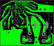
I bought several 7293, i made PCB with my own design, and using sch as per Daniel using.
But when I connect to 32vdc symmetric, suddenly one tda7293 catch fire.
I ve recheck and reroute pcb and still found nothing.
Do my '93 fake ? I bought V6 czech version.
here my layout version.
http://www.diyaudio.com/forums/attachment.php?attachmentid=655088&stc=1&d=1515255212
Attachments
I bought several 7293, i made PCB with my own design, and using sch as per Daniel using.
But when I connect to 32vdc symmetric, suddenly one tda7293 catch fire.
I ve recheck and reroute pcb and still found nothing.
Do my '93 fake ? I bought V6 czech version.
here my layout version.
http://www.diyaudio.com/forums/atta...d1515255212-optimizing-tda7294-output-tda-png
http://www.st.com/content/ccc/resou...df/jcr:content/translations/en.CD00001887.pdf
Look at the block diagram, figure 1.
If pins 7 and 13, and pins 8 and 15, do not track together on power up; or if any of the connections are unreliable, then these particular chips will self destruct. This is a well known issue that these devices have.
All it takes is a bad solder joint, or a loose connection.
Chip start to glowing bright red, with extra thick smoke when powering up this chip about 4-5 second.
No input, No output, No dummy load.
@Fast Eddie D,
I ve recheck all route and joints, all joints are good soldered.
maybe I ll reconsider new layout with 2 layers for wider track.
with 15 pin and single layer, very thin path for V Rails, when joining pin 8+15.
@nigelwright7557,
About oscillating,
My device gain more than 26x. 47k/2K2.
I think it is not gain issue.
My PSU is good. Now still powering 2.1 LM3875.
I m using 20,000uf x2, 100n for decoupling cap. No snubber.
Since no problem in other amps. I think it s not psu problem.
Did you fit a dummy zero ohms load to the input?.........
No input, No output, No dummy load.............
Did you fit the Output Zobel so that the output could see a High Frequency Load?
You should short all the leads together while handling the chip and assembling the board. Don't remove the shorting wire until you're done soldering the whole board.
You can damage the chip while installing it or assembling the board, and then when you power it up it burns up.
You can damage the chip while installing it or assembling the board, and then when you power it up it burns up.
Did you fit a dummy zero ohms load to the input?
Did you fit the Output Zobel so that the output could see a High Frequency Load?
Supposedly MOSFET amplifier doesn't need Zobel. Couldn't hurt though.
Did you fit a dummy zero ohms load to the input?
Did you fit the Output Zobel so that the output could see a High Frequency Load?
I shorted Input with ground.
I always short input with ground when testing amp.
In the past, I ve burned one Ucd class d board, when no input presence.
You should short all the leads together while handling the chip and assembling the board. Don't remove the shorting wire until you're done soldering the whole board.
You can damage the chip while installing it or assembling the board, and then when you power it up it burns up.
If you talk bout static electricity, i assembly with barefoot, cause I m standing on the floor, all my house are marble floored.
I think it s auto grounding.
My biggest question, why my chip cannot stand just +-25 vac.
On PSU Caps with multimeter, it read +- 34.8 V.
Measuring track after diode (im putting diode in every amp channel, in case reverse current) it s read +-33.9 V.
If you talk bout static electricity, i assembly with barefoot, cause I m standing on the floor, all my house are marble floored.
I think it s auto grounding.
Yes but it's not just static electricity. There could be a zap from the soldering iron too. And finally, capacitors can be charged up on the board and zap components when you install them.
A capacitor can charge up just from heating it with the soldering iron.
I always take basic precautions when installing chips (op amps too). You can check to see if there's any residual voltage before you install the device. I also short all the power leads together while assembling a board. Simple habits like this make it less likely I'll fry a component.
- Home
- Amplifiers
- Chip Amps
- Optimizing TDA7294 Output