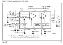
I think 1000uf+100nF is not very good either, but I wanted to keep to the datasheet schematic and to see what might be a realistic layout. Pin8 is in a bad location and makes things untidy.
Increased capacitor size.
Increased capacitor size.
Attachments
I suggest to put R6, R7 under board, and then make C6, C7, C8, C9 all 330uF Panasonic slim 50v, the first pair pressed right up against the chip. That way, when users ask for low gain, your board could do it stably.

Nice work Mark! I haven't studied the routing and flow yet, but I like the first glance. I guess I don't see the problem with C5? One capacitor on one side of the board and the other on the other side. Solder one first, then the other. Very encouraging! How big is the board overall? I'm estimating 35 x 25 mm? Might be able to go even smaller by alternating placement of big capacitors top-bottom of board at other locations! (I plan to mount the heatsink to the chassis, and let the board float). Also, would it make anything easier if we spread out the pins on the chip between the front to back rows? I've done a quick check on perf-board and they can easily be spaced out 10 mm apart. Would that allow any better routing (two traces) between the pins? Finally, since pins 5 and 11 are not connected, can we just remove the pins at the chip, omit those 2 vias completely and use the gap between pins 3 and 7 plus the gap between 9 and 13 for other routing opportunities?
Sixto.
Sixto.
Last edited:
Placing the caps on the underside means that the board needs to be lifted 30-50 mm from the chassis and it is more difficult to solder/construct. The size now is 62x40 mm, would be nice to remove 2 mm.
It would have been nice not to have used pins 5 and 11 for routing so that the board could also be used for the TDA7293 chip.
It would have been nice not to have used pins 5 and 11 for routing so that the board could also be used for the TDA7293 chip.
It would have been nice not to have used pins 5 ....
Hmm, I just looked at the datasheet for the TDA7294 and it shows pins 5,7 & 12 not connected... (I've been focusing only on the '93, thinking the difference was just the bootstrap connections between pins 12 and 14) Am I looking at an old Datasheet? Anyways,the Clip Detector circuit is there, though I'm not sure how useful it is... My starting point in this process was testing out Rod Elliott's boards, his design ignored Pin 5 and also disabled the Mute/Stby circuits by connecting them directly to the +VS traces. Quite the minimalist approach, which I tend to favor.
It's a great learning exercise for me to follow your development of the PCB layouts, I am grateful for what you have shared so far, and look forward to see where it leads!
Thank you!
Sixto
Attachments
Hmm, I just looked at the datasheet for the TDA7294 and it shows pins 5,7 & 12 not connected...
Oops, not 7, that one IS used - I meant 11 - darn that dyslexia!
Sixto
The different faces of TDA7294
There are 2 different TDA7294 datasheets.
There are 3 different TDA7294 chips that I know of.
1
On the rarest TDA7294, all 15 pins work, and it has a different datasheet, which is visually similar but also makes good mention of "Modular" just like the TDA7293 datasheet. It doesn't work well on a TDA7294 board--with all 15 pins working, it needs a board for TDA7293. The only difference between that full featured TDA7294 versus the TDA7293 is an internal setting suited to lower voltage. Today's $2 TDA7293's are the same thing, except the label is different.
2
Not previously rare, but is certainly rare today, the common TDA7294 shares schematics with TDA7295 and TDA7296, and it said "Singapore" on front. This one uses the most common TDA7294 datasheets, which makes no mention of "Modular" Also usable is the TDA7295 datasheet (and the real TDA7294 also said "Singapore" on front).
3
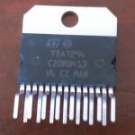
Today's TDA7294, says "Mar V6" on front and is usually not very stable; however, reducing the voltage to that which is suited for TDA7296 appears to fix it, and therefore I suggest to use the TDA7296 datasheet, mainly, much lower voltage.
Then, a question:
So, which "TDA7294" do you have?
Summary of the variants:
1 Actually a TDA7293 set up for slightly lower voltage
2 A real TDA7294, no longer manufactured
3 A TDA7296 with TDA7294 printed on it
Enjoying it may depend on identifying it first.
There are 2 different TDA7294 datasheets.
There are 3 different TDA7294 chips that I know of.
1
On the rarest TDA7294, all 15 pins work, and it has a different datasheet, which is visually similar but also makes good mention of "Modular" just like the TDA7293 datasheet. It doesn't work well on a TDA7294 board--with all 15 pins working, it needs a board for TDA7293. The only difference between that full featured TDA7294 versus the TDA7293 is an internal setting suited to lower voltage. Today's $2 TDA7293's are the same thing, except the label is different.
2
Not previously rare, but is certainly rare today, the common TDA7294 shares schematics with TDA7295 and TDA7296, and it said "Singapore" on front. This one uses the most common TDA7294 datasheets, which makes no mention of "Modular" Also usable is the TDA7295 datasheet (and the real TDA7294 also said "Singapore" on front).
3
Today's TDA7294, says "Mar V6" on front and is usually not very stable; however, reducing the voltage to that which is suited for TDA7296 appears to fix it, and therefore I suggest to use the TDA7296 datasheet, mainly, much lower voltage.
Then, a question:
So, which "TDA7294" do you have?
Summary of the variants:
1 Actually a TDA7293 set up for slightly lower voltage
2 A real TDA7294, no longer manufactured
3 A TDA7296 with TDA7294 printed on it
Enjoying it may depend on identifying it first.
The TDA7296 and TDA7295 are much enjoyed in China.
I've been tracking that.
The TDA7295 Singapore is a real TDA7294, which does happen to work a little better under-volted per the TDA7295 datasheet voltage listings.
The TDA7296 is identical to the modern TDA7294, which does happen to work a LOT better under-volted per the TDA7296 datasheet voltage listings.
Just on the really rare off-chance that anyone used these at suitable voltage, they'll work stably with most amazing imaging/resolution, and even a pretty tone at the datasheet's minimum listed gain factor. However, for this I did observe it with 220u decouplers, higher resistor values, and oversize inverting input coupler, which is a slight difference from the datasheet.
I'm of the opinion that it was used in small rooms, and probably did very well therein.
They certainly weren't short on showmanship; however, I did want more bass than that.
Did anyone know I was a cowboy? Yep, there's some wide open spaces in need of some clearly audible bass, and that's available at post #753. Even then, note the accommodations and compromises for power voltage and power output. May as well spell it out: At higher voltage the stability lessens, and I cranked up the gain to preserve the stability/tonality at some cost to imaging on one of those examples. There's two examples for you to compare. They're both quite fine, but one images/resolution a third better and other other has a third more power. Choose. Choose based on venue size. One is for a standard living room and the other is for a "great room" styled area. Neither disappoint. I checked for that already, and it was an enjoyable experience.
Last edited:
Hi all, I have been reading this thread in the past and a few days ago I received a TDA 7294 two board from jims audio. So I started reading this thread again. My old bookmarks lead to pages 41-42-43 and the assorted photographs.
But As far as I understand the latest proposed schematic, is the one on Daniels’s signature http://www.diyaudio.com/forums/atta...3316-optimizing-tda7294-output-tda7293dan.gif , but I am not sure there is a photograph of this schematic on the separate two boards.
So first of all thank you all for this great thread!
Can someone please summarize what is the preferred layout and parts for the two board version? Or point me to a recent pjhotograph?
Starting from the minikit and the included parts as far as I understand:
Better Resistors: I have an assortment of Dale CFM55, I also have takman carbon films, and hope to have all values. But can someone point out what are the most critical resistors that I should source?
Clipper: I suppose it is still needed, will have to source the components
Capacitors, last time I checked (long time ago) I had some caps that may fit this project like 220uf Panasonic
So all in all, I am looking for a cheat board 😀 A way to correlate the latest schematics from Daniel with the kit from jimsaudio, a foto or a way to correlate the boards to the schematics, and the latest proposed part values in order to source them or identify them in my stock
Thanks in advance
The TDA7296 and TDA7295 are much enjoyed in China.
I've been tracking that.
The TDA7295 Singapore is a real TDA7294, which does happen to work a little better under-volted per the TDA7295 datasheet voltage listings.
The TDA7296 is identical to the modern TDA7294, which does happen to work a LOT better under-volted per the TDA7296 datasheet voltage listings.
Just on the really rare off-chance that anyone used these at suitable voltage, they'll work stably with most amazing imaging/resolution, and even a pretty tone at the datasheet's minimum listed gain factor. However, for this I did observe it with 220u decouplers, higher resistor values, and oversize inverting input coupler, which is a slight difference from the datasheet.
I'm of the opinion that it was used in small rooms, and probably did very well therein.
They certainly weren't short on showmanship; however, I did want more bass than that.
Did anyone know I was a cowboy? Yep, there's some wide open spaces in need of some clearly audible bass, and that's available at post #753. Even then, note the accommodations and compromises for power voltage and power output. May as well spell it out: At higher voltage the stability lessens, and I cranked up the gain to preserve the stability/tonality at some cost to imaging on one of those examples. There's two examples for you to compare. They're both quite fine, but one images/resolution a third better and other other has a third more power. Choose. Choose based on venue size. One is for a standard living room and the other is for a "great room" styled area. Neither disappoint. I checked for that already, and it was an enjoyable experience.
So this is what I got from a recent jims_audio order, it is the third one that you reference . Again, Daniel thank you for your effort in this thread!
Attachments
The 220uF panasonic are good
The only specialty resistor that you'd want is a multi turn cermet trimmer for feedback shunt (not the main feedback resistor, but rather its partner).
Ways to improve that chip include, the smallest double-sided board you can find, and lower power voltage. The TDA7294 V6 Mar, chip matches up closely to the TDA7296 datasheet.
If you have trouble with that chip, here's a post on that http://www.diyaudio.com/forums/chip-amps/226437-optimizing-tda7294-output-13.html#post4153233 Post#621 here.
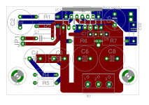
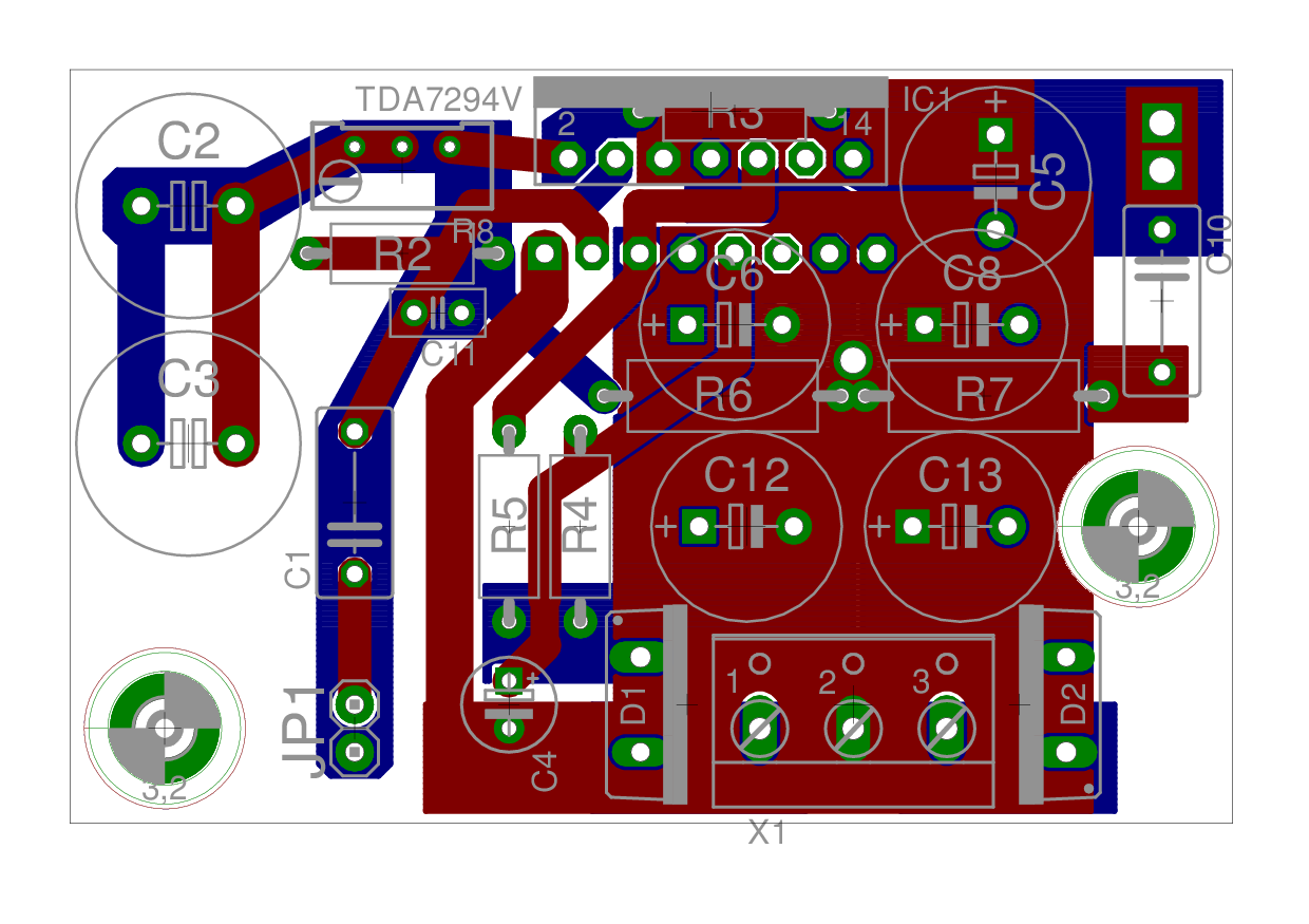
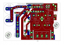
That layout is getting attractive!An attempt at Daniel's schematic, only not for TDA7293 because of pin 5. Problem with C5 still to be fixed.
TDA7294S/TDA7293V6 and TDA7293V7, use pins 6&12 for bootstrap cap hookup. These are the higher quality chips--all 15 pins work. They cost $2, exactly the same chip from both eBay and Mouser ($7) And, these versions with the higher quality bootstrap cap hookup, might be worth your time, possibly.
TDA7294V6/TDA7296 can't use that same bootstrap cap hookup, but rather those use a much lower quality arrangement instead. I suggest to save yourself some time and do not provide everlasting support for the lower quality editions. I already stepped in that one, and can verify that it would be pleasant to avoid it.
Board space:
The Inverting input coupler(s), (C2, C3) see 3vac at most, and those can use 16v rated polar caps, if you like. That's a lot smaller.
As for decoupling caps (C6, C8, C12, C13), see what the 220uF~270uF 50v caps are listed at for the size of Panasonic FM, FC, and Nichicon FW, PW.
There's sometimes two versions, but always choose the "tallboy" tall and skinny version for decoupling.
Bootstrap cap, 33uF (C5) is not very big (not as big as shown). Also, it sees only the voltage difference + 1/3rd, because signal.
As for input cap, the inexpensive Elna Cerafine Black 4.7uF works great for TDA7293's input (C1) cap, or Nichicon Muse ES 1uF for TDA7294's input cap. So, C1 needs an additional pad to support electro's too.
Omission: If C2 and C3 go through R6 for ground, that's a bad cap simulator circuit or "tone control," via RCR in the feedback (the tiny rc effect will get amplified due to gain and sound like C2 and C3 are bad caps). A good patch that keeps your groundlift theme intact is to add a tiny value capacitor in parallel with R6 to prevent treble droop. Alternatively, don't groundlift anything at the inverting input. So, at least there are those two options.
Still not completely understanding all the different versions. I will just keep to the datasheets.
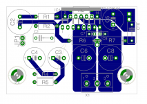
Your suggestion on moving the inv. input ground. It is important that both inputs are connected to the same point (somewhere near R6). If we connected one to agnd and one to pgnd then the voltage over R6 creates an error that is amplified.
Here is smaller layout, 5cm by 5cm.
Your suggestion on moving the inv. input ground. It is important that both inputs are connected to the same point (somewhere near R6). If we connected one to agnd and one to pgnd then the voltage over R6 creates an error that is amplified.
Here is smaller layout, 5cm by 5cm.
Attachments

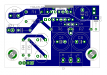
This previous version was much better in those two ways--such as making the quality control of the electrolytics, built right in to the design. No custom caps needed with that. With the electrolytics positioned closer to the chip, it will achieve lower gain more stably, therefore yielding Much higher resolution.
I certainly haven't seen a better board than this one!
I certainly haven't seen a better board than this one!
TDA7293-specific bootstrap cap hookup is for quality, so I do suggest to use the TDA7293 datasheet for the pinout information.Still not completely understanding all the different versions. I will just keep to the datasheets.
What I don't like here (beyond being difficult to build) is the ground layout. The power star point should be above the larger C6-C8. Doing this, separates the returning audio currents from the capacitor charging return currents. It looks like a ground plane, in reality, it is trying to be a very wide trace.😛
Pinout of the full featured, higher quality versions. . . see attached datasheet.
The important part for quality is the bootstrap cap hookup, with pin6 and pin12.
The important part for quality is the bootstrap cap hookup, with pin6 and pin12.
Attachments
Last edited:
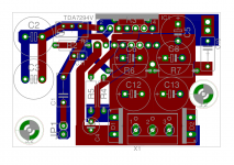
Thanks for the datasheet. This one should work for both cap to pin 12 or 14.
I also connected R4 and R5 to V+ instead of after D1.
I also connected R4 and R5 to V+ instead of after D1.
Attachments
Last edited:
Thanks for sharing the TDA7294S datasheet Daniel - I hadn't come across it before. I see it's considerably lower power than the TDA7293 (30mA typical quiescent vs 50mA, although the supply voltages are a bit different). What's not to like? 😀
- Home
- Amplifiers
- Chip Amps
- Optimizing TDA7294 Output