Bob, what's happening here is that the umbilical cable is so short that this would work well with the advanced power circuit (predrive on regs); but, unfortunately, with the simple bus rail config on the kit's boards, you've got 20,000u plugged directly into a predrive for the possibility of dull audio results.
Instead of putting the predrive on regs, which might take a different PCB, you can use a similar approach that works with LM1875 and other amplifiers that don't have separate predrive pins. The following plans aren't better than Ilimzn's advanced power circuit, except for more power and compatible with the amplifier PCB's that you already own.
Here's three ways to use the big capacitance without the big dull.
Plan A (cable trick)
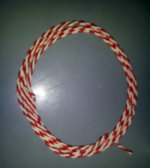
Right over at the hardware store is 20ga solid copper thermostat wire. Simply replace the short thick cable that you have from power board to amp board with 5" to 8" (in that range) of 20ga solid copper, three conductors twisted. This will provide some peak control and a slight isolation effect. Hi-fi market amplifiers that have a separate power box do exactly the same thing with their custom umbilical cables, and I have simply re-scaled that to fit within one box.
Plan B (diode trick)
Put a fast silicon (or schottky) diode into the V+ output of the power board, and put a fast silicon (or schottky) diode into the V- output of the power board.
Hook up your amplifier board cable to the diodes. Observe correct polarity (disconnect speaker and check amplifier board voltages). It is simple diode isolation--a very simple diode drop! You can re-stiffen with approximately 330u (nearby values are fine) directly at the diode output (cable side), if you need to, but that extra step is a tone option that may or may not be of benefit. This diode trick works with the cable that you already have. Diode trick can also work to correct those all-in-one power+amplifier board kits so that they're not dull (diode fits easily). Instead of the little predrive seeing epic ringing capacitance, all it can see is a diode. Think of this as like using regulators except costs much less.
Plan C (regulators)
Something much like the boosted LM317's (big output device added to expand current handling) or a discrete power regulator will be having the amplifier see the active device (just like plan b) rather than out-waiting the huge slow capacitance power board before the predrive feedback can too-slowly correct for the jolts of a running speaker. All of the plans are really for having the feedback work correctly; however, the plan with regulators can work in LTSpice simulator for the convenience of estimating the fine tuning before soldering.
Notes
Plan A (orthodox umbilical cable trick) and Plan B (unorthodox diode trick) work in a really similar way. I can't explain this but I'd just like to say that any of the above plans may prevent the amplifier from (mis)behaving like it has 20,000u amplifier board predrive power caps. And a guess: As you have already 20,000u very close to the amplifier board, I guess that you will probably not appreciate increasing the amplifier board capacitance from 20,022u to 20,220u (probably moot), unless you use one of the above plans first so that the amplifier's predrive sees just/mainly the 220u.
P.S.
If you feel the need of a replacement power supply, Post #46 with multi-parallel 2200u will sound different (sound like low capacitance supply) and can be fabricated so easily with a plain bit of copperless phenolic perfboard and three bits of 14ga solid copper wire for the traces. This supply works along with plan A above, a short length but 20ga solid copper cable umbilical cable to connect to the amplifier board. With the smaller capacitance, the umbilical cable can be shorter length than the cable you'd need for your big power boards. Post 46's power supply is a low component count build and instead of the bulk of a CRC filter, post 46 schematic uses quiet diodes like fast/soft silicon or Fairchild Stealth schottky to reduce the component count, which is not better than CRC but it is lower cost and easier to build.
Can you describe the "less gorgeous" effect? Is it treble, bass, or somewhere in the midrange? And, do you have a schematic or perhaps list the component values?Jay said:The first moment I heard the sound, I didn't recognize the sound of TDA7294 I have been familiar with. With the last change the sound is less gorgeous but more musical. I like the latest setup with 2x220uF, whatever causing it
P.S.
Instead of the 220u, if you missed the sound of the little caps that came with the kit, you can use 100u caps, which is about minimum.
Last edited:
Can you describe the "less gorgeous" effect? Is it treble, bass, or somewhere in the midrange? And, do you have a schematic or perhaps list the component values?.
Hmmm... speed? transparency? I guess it is what made Bob think that the amp is faster than 3886. Actually the TDA slew rate is only 10v/us. It is what make the amp beautiful playing orchestra or at least jazz.
The component was as per your suggestion, mentioned in the previous posts. Input cap doesn't matter much once we use good parts. Tried some oilcap also.
Instead of the 220u, if you missed the sound of the little caps that came with the kit, you can use 100u caps, which is about minimum.
Actually I never tried small caps. Just what ilimzn has mentioned, it is the ESR that matter most in this case, not the capacitance. The bigger the capacitance, the higher the ESR. Expensive 1000uF cap might have equal ESR with 220uF cheaper cap. So, I have always assumed that my standard Black Gate 1000uF is small enough not to dull the sound.
Larger = warmer but less clear, and smaller = clearer but less bass.Input cap doesn't matter much once we use good parts. Tried some oilcap also.
The quality or resolution of the cap matters more with bigger gain or matters less with smaller gain. I tried the TDA7294 at higher gain and it sounded more dynamic, of course, but the input cap and nfb cap got to be quite the mess of bypass caps before I was satisfied with their quality.
Anyway, you could try turning up the gain a bit to see how much is needed to bring back those fun dynamics.
Increasing gain is another way to say decreased feedback. 🙂 It will increase the amplifier's sonic signature, increase the THD and increase the dynamics too.
I'd be very interested to know how much gain is needed.
If I knew your previous and current NFB cap, feedback shunt resistor and feedback resistor values (exactly), I could attempt to generate a middle ground setting, including a middle ground audiometric balance at the bass.
Note that the dissipation limit applies to a continious, not music signal as music (even highly compressed) has a high peak to average power ratio. Things do change quite a lot if it's used in an active system, for instance as a sub or midbass power amp, for the particular bandwidth things can get hot. But for full range listening, it's not a problem.
I've made several amps with this chip. Some friends of mine are now developing an idea for a hybrid amp using the TDA7293 chip in a way no other hybrid with a chipamp does, so that will give us some new data.
I have used all sorts of power supplies on these and the best I have found (apart from simply regulating the input stage power rails) is not to go overboard with the power supply caps. The basic idea being the same as daniel suggests, limit the maximum amout of energy one can pull through the chip, providing enough for musical peaks but not enough to drive it to it's maximum ratings for a longer time. My favorite is RCRCRC filtering. Pre-regulation is also a good idea and mostly the improvement here comes from not having the higher harmonics from rectification spill over into the driver stage via the MOSFETs reverse transfer capacitance. I've used this approach on other MOSFET amps, most notably on a hybrid with 3 pairs of laterals in the output and it does indeed make a difference.
Regarding MOSFET performance - the DMOS parts in the TDA729x are most similar to laterals. A good clue id the required 8 or so V to drive the top part to full conduction.. The somewhat peculiar way the TDA handles phase splitting for it's quasicomplementary output stage has a consequence, the bottom MOSFET actually follows what the top one does and if the top one makes errors, so will the bottom, and with a slight delay. Adding a small extra current to offset the crossover point actually changes the sound quite a lot but I will leave the description to subjective tastes.
One other topology that I have not mentioned is a sort of current dumping approach with an external pair of MOSFETs (IRFP240/9140). This worked very well but is not really cheap as it also requires an extra smaller MOSFET of similar technology (IRF520) for temperature stabilisation of the output pair. But, it does make the amp into a very vapable performer even into rather low impedances - and with properly adjusted bias for the extra output, the output behaves like a currnt multiplier, making the TDA see a higher load impedance, which it can drive much more easily. The sound from this is much more 'fresh' and less 'MOSFET' - the latter being a sort of subdued character that often happens with MOSFET amps.
Regarding layout - either tightly packed point to point (I use a perfboard to mount the chip then wire it up) or two layer PCB. Single layer is also OK but the problem is that you need to run traces 'behind' the chip footprint, where the heatsink should be, so you limit your options on heatsinks, unless you bend out the pins of the chip differently. I've used this on a perfboard as well, bending them up so the chip can be mounted flush with the PCB and the PCB is then used to clamp the chip to the heatsink, using an aluminium spacer to make up for the space between the surface of the plastic part and the surface of the heatsink tab. This also spreads the clamping force out more evenly - overtightening the tab WILL bend it, and in extreme cases cause unexpected catastrophic chip failure. Having more PCB area around the pins helps a lot with layout.
Bootstrap - there is a source of distortion generated by the diode from the input stage rail to the bootstrap cap. The VA section therefore operates from this power supply as long as the output + bootstrap voltage is lower than the rail, and when it gets close to the rail the bootstrap cap internally lifts the current source of the VAS stage up, kind of like in a class G amplifier. However, this is a transient in the power supply of the current source which gets transferred to the VAS directly thorugh the current source residual capacitance. This is not large, but the VAS impedance is, so it does make a difference. I find this a bit odd WRT the design of the chip, it would have actually been simpler if the current source was bootstrapped all the time, not just on peaks, but I guess the breakdown voltage for that part of the chip would then be above that attainable by it's manufacturing process. The distortion itself is less objectionable than some as it generates some second and fourth harmonic components, i.e. even harmonics.
Power supply schematics - beware of large filter caps after rectifiers, especially with toroid transformers, UNLESS the transformer is wound with that in mind. Large filter caps reduce the conduction angle of the diodes and increase peak currents when they do conduct, at some point you get to current limiting through core saturation which is BAD. The effect on the transformer is heating up, and the effect on the power supply is not that horrible BUT you get a sudden and HUGE rise in stray magnetic field from the transformer, which will gladly induce currents everywhere in the circuit, where there should be none. This will be an intermodulated mixture of 100/120Hz ripple and your music signal, something you surely don't want. One way to battle it is to use a hugely oversized transformer, which is what people usually do as a kneejerk reaction, not knowing why it works - because a bigger transformer will be able to handle higher peak currents without saturation. If you have no option but getting finished transformers, this might be the way to go. Another way is to specify a 'soft' field density to the winder - say 1.2T instead of the standard 1.6 or 1.7T. This makes a larger part capable of higher peak currents and less susceptible to say DC in the mains, but still smaller than the required oversizing of a standard wound part, you might save some $ and get better performance. Finally, you can also deliberately introduce current limiting resistors in series with the rectifier or capacitors, forming an RC(RCRC...) filter. This can give a rather dramatic improvement even for small resistor values, like 0.1 ohms. Not only does it limit current peaks, and makes it an easyer job for the transformer, it also provides damping for any resonant circuit that arises from the stray inductances of the trafo, ESL and C of the cap. With pre-regulation, the input side caps of the regulator (i.e. filter caps for the rectifier section) can be reduced, keeping the output caps high. This approach alsmot completely separates the audio currents passing through the caps in parallel with the preregulator output, i.e. in parallel with the chip's rails, and the rectification peak currents in the filter caps, this is always highly desirable, as any mixing across a non-linear element such as capacitor ESR (which is partially chemistry generated!) produces intermodulation, up to frequencies where the chip's (or in general, amplifier's) PSRR cannot well cope with them.
I'd be very interested to know how much gain is needed.
If I knew your previous and current NFB cap, feedback shunt resistor and feedback resistor values (exactly), I could attempt to generate a middle ground setting, including a middle ground audiometric balance at the bass.
No change to NFB caps: 2x100uF ELNA
FB1=56K Sfernice
FB2=2k5 Tantalum
Bootstrap: 2x33uF (ELNA or Panasonic) to 68uF Philips KO. I think this is an improvement as I like the sound of the Philips KO.
PS Off-board: 8x3300 Nichicon
PS on-pin bypass: 100n MKT Philips
PS on-board: 2x470uF ECON (I like this one too) to 2x220uF Panasonic CE HF. I choose the Panasonic because it looks good and bigger but I'm not familiar with the sound.
Mute: 10K
Standby: 22K/10uF Samsung
Input resistance: 10K
Input cap: 1uF ERD (With the last setup I tried various cap, from 470n to 1u5, no critical difference).
BTW, there is big difference soundwise between the standard FB arrangement versus the complex one. With the standard setup, I always feel disturbed and want to turn off the system. With complex FB setup, I cannot stop listening to music. Last night it was hard for me to switch off the amp. I listened to jazz until 3 o'clock in the morning.
If common people have to compare both systems, they may not be able to hear the difference. And if they could, they may not be able to pick the better one. But for me it is like sky and earth, when one passed the "I can't get enough" test and the other one pass the "Turn it off, please" test.
What you can get with the complex FB setup is a high input impedance with minimal feedback and feedback resistance, without losing the drive. Contrary to it, your setup is strange, where you use 10K lowish input impedance and 60K highish feedback resistance.
Your 60K/2K7 FB resistances is probably not too low nor too high. It is problematic actually, to find a win-win setup. With the complex FB OTOH you can get better drive even with lower feedback. I don't have my simulator for a few weeks now so I cannot discuss the technical aspect for the moment. But why not try for yourself (yes you will have to solve some issues, but not as complex as designing discrete amp). If you have good ears, you don't need technical skill to get the best sound. What you need to do is to build everything and decide by ears which one is the best.
Regarding MOSFET performance - the DMOS parts in the TDA729x are most similar to laterals.
Cool. So that's why it sounds close to latfet. Hitachi latfet sounds better but much more expensive. May be the TDA7294 can be a cheap alternative to a good mosfet amp in class-B.
Bootstrap - there is a source of distortion generated by the diode from the input stage rail to the bootstrap cap. ---- The distortion itself is less objectionable than some as it generates some second and fourth harmonic components, i.e. even harmonics.
Ehm, that's the reason to keep the bootstrap. I don't like distortion, whatever the order. But if to choose non-pleasant distortion spectrum versus the pleasant one, of course I will choose the pleasant one. I guess, sometimes we don't know whether the distortion we get from an amp is pleasant or not, so a bit of increase of the 2nd order will ensure good spectrum.
P3A builders prefer the bootstrap approach. So are Fetzilla builders. In the TDA7294 I see current mirror, many current sources, and if regulation is added to the input stage, most probably the distortion spectrum is of unpleasant type.
The thing with distortion is that you can in principle mask unpleasant distortion with more pleasant one but it comes at the expense of resolution and micro-dynamics. Unfortunately, you can't undo anything in the signal once it's done.
Current mirrors and sources do not guarantee neither a lack or presence of distortion in themselves just like one can use the best possible components in a bad toplological design and get mediocre or even horrible results. I personally try to avoid any knee-jerk reaction to a schematic, sometimes there is more logic and depth to things than is immediately obvious. Regarding the VAS bootstrap, you cannot avoid the current source. The only thing that changes is the actual power source for it and because that changes, it generates distortion which would normally not be there.l However, without bootstrap (but no extra voltage to drive the output stage) the output stage input and reverse capacitance non-linearity when Vd apporaches Vg produces much more insidious distortion... i.e. it;s not the regulation for the input stage but the higher voltage for the input stage that can enable you to exploit the lack of a bootstrap cap retaining full swing but without the distortio. Your comparison to classic bootstrap is wha I mentioned re it would have been better from the standpoint of distortion if the VAS was always bootstrapped (rather than a current source approach) but alas that is something you cannot influence.
Current mirrors and sources do not guarantee neither a lack or presence of distortion in themselves just like one can use the best possible components in a bad toplological design and get mediocre or even horrible results. I personally try to avoid any knee-jerk reaction to a schematic, sometimes there is more logic and depth to things than is immediately obvious. Regarding the VAS bootstrap, you cannot avoid the current source. The only thing that changes is the actual power source for it and because that changes, it generates distortion which would normally not be there.l However, without bootstrap (but no extra voltage to drive the output stage) the output stage input and reverse capacitance non-linearity when Vd apporaches Vg produces much more insidious distortion... i.e. it;s not the regulation for the input stage but the higher voltage for the input stage that can enable you to exploit the lack of a bootstrap cap retaining full swing but without the distortio. Your comparison to classic bootstrap is wha I mentioned re it would have been better from the standpoint of distortion if the VAS was always bootstrapped (rather than a current source approach) but alas that is something you cannot influence.
The thing with distortion is that you can in principle mask unpleasant distortion with more pleasant one but it comes at the expense of resolution and micro-dynamics.
Yup. Pleasant sound with lack of resolution and micro-dynamics, versus unpleasant sound with amazing resolution and micro-dynamics 😀 Of course there is always better option, but often with a different schematic.
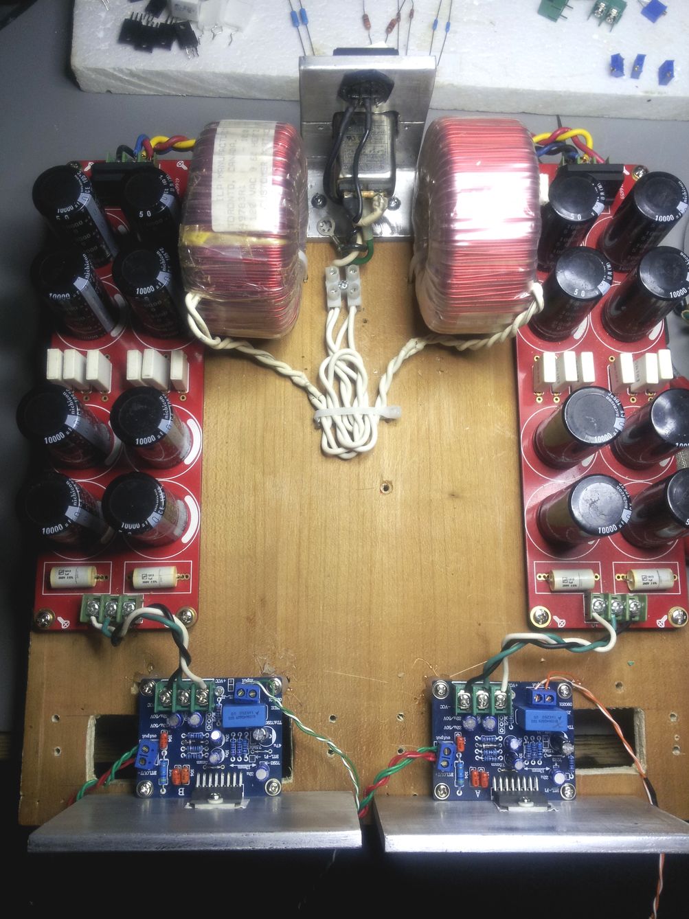
Late start for me today. The dual transformer (ApexJr 125 VA) amp is up and running. I'll just repeat this $30 two channel solution is scary good even at a stock build.
I saw only one mention, but the highly regarded Wima caps are usually closer to the sizes used on this board. Might those be better than trying to fit the round radials. I have gobs in the stash.
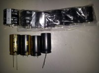
I'm going to build at least one DIY/P2P power supply for the 200 VA toroid primarily because my audio memory wasn't good enough to tell if the larger single transformer had a little more push on the bottom - as was my first impression. ( As in my experience with the LM3886 builds, though no tubes here, there is still the need for a 20 - 30 minute warm-up to really get the full bloom working) I did a quick check for 2200 and 3300 caps at RS and came up with $50 to $100 for the numbers needed. Even at Mouser they cost more that the full kit. I don't mind paying those amounts if the benefit warrants the cost, but I did find ten 3300 uF in the stash - but are different mfgs. Does mixing cause any problems (other than ugly)as long as the specs match?
I can buy some "thermostat wire" for the umbilical Daniel describes, but I see some vendors list doorbell wire as the same. I have the solid bell wire - useable?
Sorry to be lagging so far behind but I am reading, enjoying and learning from the advanced discussions. For my part, this may be the time I venture into perf-board/P2P adventure to remove the size limitations of my current board - if a new PCB doesn't emerge.
I saw only one mention, but the highly regarded Wima caps are usually closer to the sizes used on this board. Might those be better than trying to fit the round radials. I have gobs in the stash.
I'm going to build at least one DIY/P2P power supply for the 200 VA toroid primarily because my audio memory wasn't good enough to tell if the larger single transformer had a little more push on the bottom - as was my first impression. ( As in my experience with the LM3886 builds, though no tubes here, there is still the need for a 20 - 30 minute warm-up to really get the full bloom working) I did a quick check for 2200 and 3300 caps at RS and came up with $50 to $100 for the numbers needed. Even at Mouser they cost more that the full kit. I don't mind paying those amounts if the benefit warrants the cost, but I did find ten 3300 uF in the stash - but are different mfgs. Does mixing cause any problems (other than ugly)as long as the specs match?
I can buy some "thermostat wire" for the umbilical Daniel describes, but I see some vendors list doorbell wire as the same. I have the solid bell wire - useable?
Sorry to be lagging so far behind but I am reading, enjoying and learning from the advanced discussions. For my part, this may be the time I venture into perf-board/P2P adventure to remove the size limitations of my current board - if a new PCB doesn't emerge.
Attachments
Last edited:
At Mouser, 6 of 2200u per rail, there's two rails so 12 caps total, and at $1.50 each, 12*1.5= $18. 2200uF 50v Aluminum Electrolytic Capacitors - MouserI did a quick check for 2200 and 3300 caps at RS and came up with $50 to $100 for the numbers needed. Even at Mouser they cost more that the full kit. I don't mind paying those amounts if the benefit warrants the cost, but I did find ten 3300 uF in the stash - but are different mfgs. Does mixing cause any problems (other than ugly) as long as the specs match?
I would suggest to buy 2 extra caps in case you want to adapt this to a CRC power supply.
Probably we don't want to mix different caps within a power supply reservoir.
Mouser also has the Fairchild Stealth diodes, which do cost a bit, but practically any soft/fast diode with at 16a or more and 200v or more will do. For center tap transformer hookup with one bridge rectifier, you might want four of the 16a diodes. Or, for dual secondaries transformer hookup with twin bridge rectifier you might want eight of the 8a diodes. There's not much difference either way, so whichever you like is fine.
Yes, probably, just check the gauge with your wire stripper tool and see.I can buy some "thermostat wire" for the umbilical Daniel describes, but I see some vendors list doorbell wire as the same. I have the solid bell wire - useable?
P.S.
Your stash of 3300u caps can work great as speaker protectors.
3300u||3300u = a low loss 6600u speaker protector cap.
Last edited:
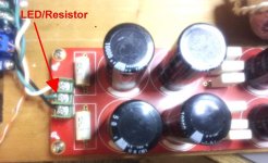
Thanks Daniel. The bell wire is 1 mm on my calipers. I didn't see those Mouser caps this morning but that's not surprising 🙂 I'll place an order later today. Using your crystal ball, can you foresee anything, other than the diodes, I should add preemptively? I have the LEDs and resistors for the PS indicator/safety mod.
When I tried to calc the average between the two examples, I came out with 330u with 1k2 vs 33k. There's a little bit more of that warm sound, but if you want the pretty treble and the warm sound together, that's a lot more like 100u with 3k3 vs 100k (or just barely slightly less than the 100k feedback resistor, like 180k||180K for 90K). So, one option is warm with regular treble and the second option is warm with airy treble. I'd suggest to test drive the second option (100u+3k3 vs 100k), which is not boring. However, I'm quite curious about your advanced feedback and will have to try it.What you can get with the complex FB setup is a high input impedance with minimal feedback and feedback resistance, without losing the drive. Contrary to it, your setup is strange, where you use 10K lowish input impedance and 60K highish feedback resistance.
Your 60K/2K7 FB resistances is probably not too low nor too high. It is problematic actually, to find a win-win setup. With the complex FB OTOH you can get better drive even with lower feedback.
Last edited:
Possibly some favorable varieties (Panasonic FC, Nichicon FW, Nichicon KZ, etc. . .) that you can try for NFB caps and amplifier board power caps, especially since caps in that range are inexpensive and shipping is not.Thanks Daniel. The bell wire is 1 mm on my calipers. I didn't see those Mouser caps this morning but that's not surprising 🙂 I'll place an order later today. Using your crystal ball, can you foresee anything, other than the diodes, I should add preemptively? I have the LEDs and resistors for the PS indicator/safety mod.
And a pair of 0.22R 5w in case you want to adapt your power board to a CRC. Ordinary wirewound of 0.22R and less is not significantly inductive, so the inexpensive Xicon will do fine.
Also, a Nichicon ES 1u cap for a good "standard" hi-fi input cap performance, to have around for comparison purposes. If a fancy audiophile cap can't beat that Nichicon, well that's informative.
Fun and easy bypass caps (for improving NFB cap performance) include 22n and 10n polyester (easily found at the radio shack), and a selection of 0.47u and smaller Nichicon from Mouser.
Last edited:
Before parts swapping tinkering/tuning with the amplifier, I'd like to see an LED's, amber or red, per each rail on that power board and a drainer resistor per each rail. Parts: 2 led's and 4 of 5.6k resistors. Each LED needs its own resistor. Each rail also has a 5.6k drainer resistor. Of course you could do 2 led's per rail if you wanted to--they'll drain it down 1.9v per rail, shortly after power off. The combination creates a dual-duty drainer and a safety indicator, useful for. . . waiting for the LED's to go dark before tinkering with the amp. The drain is very mild (doesn't interfere with audio performance) and will take a little time for the LED's to go dark. The LED's are inexpensive and they might save your life.
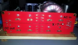
Daniel, Just a double check. Is this correct?
Attachments

Well, that's really close to right, except that one of the LED's is reverse and won't light.Daniel, Just a double check. Is this correct?
Remember 0v is 35v higher than negative rail.
An externally hosted image should be here but it was not working when we last tested it.
That's a pretty good drawing except that some types of LED's are marked backwards, such as white high brightness is sometimes opposite of amber and red. They can break if installed backwards, and so, you might want to buy several LED's rather than just two.
see also
The spots for 3k3 are at least 1/2w resistors, the 10R is at least a 3w resistor, for longevity.danielwritesbac said:
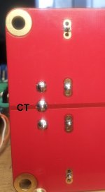
I do have a question: Do you have a center tap or a dual secondaries transformer?
Last edited:
This is for the kit build PS I already have. The new P2P stuff is on order. From your post it looks like the drain resistors belong before the caps - correct?
I just flipped the icon in the drawing program but am aware of the LEDs polarity thing. I have about two dozen LED on hand from other projects - red, green and amber - but I'm one resistor short that I'll get at RS tomorrow.
I just flipped the icon in the drawing program but am aware of the LEDs polarity thing. I have about two dozen LED on hand from other projects - red, green and amber - but I'm one resistor short that I'll get at RS tomorrow.
Attachments

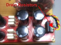
Ah well, the drain resistors don't go on the AC side, since we don't need to drain the power company. On that board, drainer resistors go underneath, at C1 and C2.
notes:
When using 1/4W resistors, 3k3 drainer resistors can be made up of 3 of 10k (3/4W 3k3) at C1, AND 3 of 10k (3/4W 3k3) at C2.
Both rails have identical drain.
That's an extremely light/slow drain--good for audio quality, bad for fingers, and therefore requires adding LED warning indicators for better safety.
Radio shack's thick variety pack of resistors are Xicon, with quite good quality and nice thick leads. To make the experience faster, I have a colored containers like the red container has resistors in the range of 1K to 9K, the orange container has resistors in the range of 10K to 99K, and then the search is not too long.
I have some of those yellow painted LED's and will go measure one of them to estimate an appropriate resistor value--painted LED's may have a voltage drop anywhere between 1.6v to 3.2v, so I'll go check. The schematic has the resistor value for a clear body red (1.7v) or amber (1.9v), However a white LED (~3v), regardless of the paint job would take a different resistor.
At the radio shack, don't forget the white canister of gel flux, because, using a toothpick, you can dob any non-shiny connection and re-heat to secure the connection (as shiny as a chrome Buick bumper). I'd never be able to do tight p2p perfectly without it. Their gel flux is also perfect to combat those nonstick gold plated vias/holes. It is also fairly vital for high quality re-work like component swapping.
Bob, here (attached below) is a layout method, for perfboard.
This easy construction method has three thick solid copper conductors. That photo below is not specifically your power supply, but really the point of these simple power supplies is a good head start with decent performance. And, then you accessorize to suit for a given transformer--all transformers have unique needs. The cap tank is universally useful but there are many rectifier and filter options, so I will attempt to re-draw it modular and this will take a little while.
Attachments

Last edited:
I didn't find the Radio Shack painted LED's but I did find several different models of colored body LED. They're all internally yellow LED's 1.86v to 2v range. You can check yours by just lighting one up (low current low voltage wall pack and don't forget the LED's series resistor) and measuring the forward voltage drop across the LED, with DC voltmeter.
Just enough current to light it is the diode knee voltage. Its slightly lower than the average figures, but knee voltage (switch-on voltage) is what we need for the calculator and for a bit of safety derating.
Next: LED Resistor Calculator
We put in 37 for voltage, and we put in LED diode drop of 1.86 (put your real figures here).
Current highpoint is led constant current datasheet figure multiplied by 0.43, which is max (and definitely try less, until the output just starts to decrease, which is the actual max). However, a 1/4w resistor is the real limiting factor here. Decrease current until the calculator's "safe pick" resistor is 0.250mw or less.
Result:
With 1.86 diode knee voltage, I get 4.27ma, or in other words. . .
8.2K resistors.
Of course, you could use 10k resistors--just slightly dimmer light.
Last edited:
The faster I am, the behinder I go!
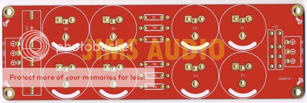
I see one must be more precise when placing arrows 🙂 I was just too lazy to unscrew the board at the time to take a photo. When I did the 0V - CT element is not so obvious as in the diagrams/examples. Before I build a bomb, where to connect the drain resistors at C1 & C2? It doesn't appear to be a two layer board from what I can see - though that may be deceptive. I don't see any links to the pads on either end.
Also. when using the LED resistor calculator it appears a pot/rheostat is needed to get "actual values". Is that correct.
We are a stretch away from the TDA chip fixes, but I (and hopefully others) appreciate the mini PS tutorials. 😉
Attachments

- Home
- Amplifiers
- Chip Amps
- Optimizing TDA7294 Output