And for all those designing and winding their own transformers themselves, I have found very helpfull reading regarding trasformers (apart from the all-time reference Chapter 5 of RDH4) here, from Turner Audio:
http://www.turneraudio.com.au/education+diy.html
scroll down and you will find a lot of articles on transformers.
Also, a very good book on transformers (including AF Txs) is "Electronic Transformers and Circuits" by Reuben Lee, which can be dowloaded from Pete Millet's extensive library:
http://www.pmillett.com/Books/Lee_1955_Electronic_Transformers_and_Circuits.pdf
Regards,
Evangelos
Thanks kenev.kenev said:
resident,
It seems that the 0.50 mm lamination is the "standard" lamination (max. flux density of 1 Tesla), while the 0.35 mm is grain oriented lamination (it says "lamierino grani orientati") equivalent to M6 grade (max. flux density of 1.4 Tesla).
So M6 is equivalent to grain oriented lamination?
One more question. European standards are EI-84,96,108,120,etc, are the dimensions of these the same with US laminations?
By the way, nice jig! And thanks for the nice links.
resident said:
One more question. European standards are EI-84,96,108,120,etc, are the dimensions of these the same with US laminations?
Sort of. The European standard refers to the entire width of the lam in mm. The core will be 1/3 that dimension. In the US standard, the width of the core in inches is designated. The core size is stepped in 1/8", but described in hundredth's of an inch - sort of (confused yet?). So a 1" core is EI-100, 1 1/8" core is EI-112, 1 1/4 is EI-125, 1 3/8 is EI-137, etc..
The closest to the EU EI-84 (28mm core) be the would be the US EI-112 (28.5mm core).
Sheldon
thanks Sheldon
So they're not the same, but have the same ratios.
Window is 1/2 the tongue and total length is 3*tongue, like EU standards....
My winding machine is almost ready. The meter is missing and some bearings! I'm planning to build a lot of projects 😀
OK, be cool and start slowly.... what to build first a guitar amp or hifi amp? I prefer a SE as I allready have a KT66 PP amp. I'd like to try the famous 2A3 or 300B tubes....
But as my band will start some gigs sooner or later I'd like a Bassman or Bandmaster clone too. 🙄
I understand the complexity of the OPTs but power transformers are simple, right? One winding for the 220V and one for the secondary. Am I correct?
Yvesm said:Some stuff to dig into:
http://www.dissident-audio.com/Pst/Bobineuse.zip
http://www.dissident-audio.com/Pst/Pst.zip
http://www.dissident-audio.com/Pst/DocPst.zip
http://www.dissident-audio.com/Pst/SE-WINDUP.zip
Sorry for the mess and French language, photos and schemos may help anyway.
Yves.
Yves,
I really liked your DIY winding machine. What I found excellent is the wire guiding mechanism. I would like to make something similar for my winder too. There are a couple of thing that I would like to ask you about this. I studied the AVANCE circuit and I want to ask you two things:
1. What kind of Hall effect sensor do you use? Since I don't know anything about Hall sensors, I try to guess its operation. As far as I can understand it, the Hall sensor feeds pulses (12 Volts?) to the 555 timer and 4029 counter (1 pulse for each turn of the bobbin). Could I replace it with a reed switch?
2. What kind of stepper motor are you using?
Thank you.
Regards,
Evangelos
I have a mechanical counter on my winder. It's simple and can also go backwards. Invaluable when removing some turns, However the whole machine is manual and I must figure out how to add a motor to it.
I'm about to wind up a transformer using Yves cool little program. I'm curious though as to how important it is to wind in perfectly neat fashion. It's pretty easy to make sure the turns count is accurate, so that shouldn't be a problem. And interleaving seems straightforward. But I've heard mention of scramble winding techniques, which I assume to be more or less random winding across the bobbin, instead of perfect layering. What are the advantages/disadvantages of doing it this way?
Sheldon
Sheldon
Sheldon,
Rule of thumb in my shop is to scramble wind the primary and perfect layer wind the secondaries. When I say scramble winding, the wire is going to do this anyway. It will backtrack and jump around a good bit regardless of how tightly you attempt to control it. Best to get your fingers about a third of a meter away from the bobbin and just "influence" the wire to wind in a way that ends up with a flat final surface to apply the dielectric to, This will aid with the secondary windings.
In very high performance OPT's we wind only in single layers for the secondary. I usually attempt to design the 4 ohm winding with a wire size that allows this, Then parallel enough 4 ohm windings to make up the required circular mils of copper to carry the current. This usually means two complete primaries with secondaries interleaved. Since a secondary winding shields all further windings from the E Field event, my secondaries are never more than two layers deep.
Means this for push pull:
Pri A1 half of the full primary turns and half of the needed wire size
S 4 ohm one fourth of the needed wire size, all of the 4 ohm turns
S 4 ohm one fourth of the needed wire size, all of the 4 ohm turns
Pri A2 half of the full primary turns and half of the needed wire size
S 8 ohm added turns needed wound bifillar for full wire size needed
S 16 ohm added turns needed of the full wire size needed
Pri B1 half of the full primary turns and half of the needed wire size
S 4 ohm one fourth of the needed wire size, all of the 4 ohm turns
S 4 ohm one fourth of the needed wire size, all of the 4 ohm turns
Pri B2 half of the full primary turns and half of the needed wire size
So the secondaries are connected in series, outside of the coil and the primaries are connected in parallel. If you make the Pri B 2 one wire size bigger than the rest of the primary wires, the two halves of the winding will balance to within one ohm, when paralleled when using american standard wire gauge sizes. I do not know how much you must increase with metric wire gauge to accomplish this..
Single Ended uses the same layout, but, the primary turns are divided into fourths, each wire used is the full size needed for the current and each primary section is connected serially instead of parallel. The last pri winding is not increased in size.
It is also entirely useful to allow a 3mm space between the winding edges of the secondary windings and the form. We use 3mm wide creped paper tape, with adhesive, to build up a space on either side of the well and then wind into the remaining space. You will have significantly less distortion if you do this. It is also a much safer coil.
Bud
Sheldon,
I'm not an expert on this subject, but I will say that, when I'm winding a transformer, I always try to have an even layer, either primary or secondary. I try not to have any wire crossings. Not that any "scramble" winding in the primary will do any harm, but, except that I like a neat layer, this is also critical for filling the window space, when you are at the limit. I must also note that I use insulation between each layer of primary windings.
You can see a sample of my winding in the previous post of this thread:
http://www.diyaudio.com/forums/showthread.php?postid=1344616#post1344616
Regards,
Evangelos
Thanks for the great detailed answer Bud. A lot of good information in there. I'm doing an SE transformer, and I think for this first try, I'll just do a single 8 Ohm winding.
Here's what I'm going after: http://www.diyaudio.com/forums/showthread.php?postid=1528269#post1528269
Wow Evangelos, I'll see how neatly I can wind. But I guessing that I'll end up more as Bud suggests - we'll see. My plan is use insulation only between primaries and secondaries.
Sheldon
Here's what I'm going after: http://www.diyaudio.com/forums/showthread.php?postid=1528269#post1528269
Wow Evangelos, I'll see how neatly I can wind. But I guessing that I'll end up more as Bud suggests - we'll see. My plan is use insulation only between primaries and secondaries.
Sheldon
Sheldon,
What kenev says about his winding technique is important to know about. How you choose to wind, either section winding, as he shows, or bulk winding as I speak about, are chosen based upon the volts per turn that the coil will be subjected to. You must consider DC and AC voltage here.
The real determinant is longevity in service. In a bulk wound coil you do not want to exceed 900 volts combined potential, even with first quality vacuum impregnation, with a 100% solids compound. If you were to leave an unpotted, bulk wound coil, subjected to this level of stress , the life expectancy would be in tens of hours. Potted, with Dolph 1105 at 30 inches of mercury vacuum load and properly baked out, the same coil will last 300K hours in service. If you drop to 500 volts potential, an unpotted coil will last a few tens of thousands of hours and a potted one effectively indefinitely.
Using layer section winding, with either a layer material that will absorb the potting compound, or an impervious one, with a good dielectric strength, and keeping the voltage per layer below 100 volts combined, you can run an unpotted transformer at 900 volts stress for tens of thousands of hours and a potted one effectively indefinitely. In all cases corona death is the culprit and corona begins it's work at 30 vac. Something to note here is that corona is most active at any dielectric discontinuity. Meaning tape edges and layer edges, if the winding is brought out to the edge of the dielectric material.
There are performance considerations when using layer section winding strategies vs bulk winding and there will be audible differences between two otherwise identical transformers, built to the two standards.
If you are determined to use transmitter tubes for your amplifiers, then the layer section winding configuration is your ONLY choice and at that level of performance, margins must be left at either end of the winding layer, for every layer in the coil. These margins begin at 3mm, for 900 volts, and grow with increasing voltages to 6mm at 3500 volts.
For SE OPT's, with a single output impedance, you can get away with a three primary sectioning, with the secondary in four layers, in the two sectors created by the three primary windings. Something like this:
Pri one third the turns with full wire size
Sec one fourth the wire size and full turns
Sec one fourth the wire size and full turns
Pri one third the turns with full wire size
Sec one fourth the wire size and full turns
Sec one fourth the wire size and full turns
Pri one third the turns with full wire size
The primary is serial connected outside of the winding and the secondary is parallel connected. Extra winding interleaves will be beneficial with layer section winding but will make no audible difference in a bulk wound coil.
Bud
BudP said:Sheldon,
It is also entirely useful to allow a 3mm space between the winding edges of the secondary windings and the form. We use 3mm wide creped paper tape, with adhesive, to build up a space on either side of the well and then wind into the remaining space. You will have significantly less distortion if you do this. It is also a much safer coil.
Bud
Bud,
This is a really interesting technique.
Could you please explain a bit further how this approach reduces distortion?
Also, what is this "3mm wide creped paper tape"? Could you post a photo of it?
Regards,
Evangelos
kenev.
Actually this just comes from the layer section techniques you are copying.
In a manufacturing environment, where a fixed length cardboard winding tube is used, typically 24 inches long here in the US, a number of coils are wound at once. Layer insulation is fed in while the tube is spinning at maximum rpm. This feed is supposed to come just as the traverse control switches direction for the next layer.
Since it is hand fed, this layer paper goes in pretty close to the reverse point and this causes an uneven number of turns per layer. Also, there is no edge locking for the last wire in any, layer so it is free to slip around. The typical way to get past this is to leave margins so that when the coils are cut into proper lengths with a band saw, there is enough margin left that the coil wires don't slip out.
Many years ago I made some experiments with primary and secondary phase coherence, using a layer wound coil and a bobbin wound coil, of roughly the same construction. The layer wound coil had less phase distortion as the saturation point of the core was reached. Since this was a 60 Hz only test it seemed unlikely that any other factor but corrupted antenna event, within the window could be the cause. I then made a coil with many many one and two turnn windings in a number of layers as a secondary and interleaved them with a sectioned primary, much as I describe for SE OPT construction. I then looked at various secondary windings with a scope, when they were hooked in opposition, so that I could detect phase differences between them at different points in the coil window.
It turns out that the core material is causing the mag field, created by the primary and contained within the window, to become corrupted at ever increasing distances from the core, as saturation is approached. The best distance from the core turned out to be around 3mm. When I wound another coil with both primary and secondary at 3mm from the core, I found no special difference from the coil wound with full width primary layers. There also did not appear to be any additional roll off, as the frequency rose, between the two methods.
Using a bobbin wall, manufacturing tolerance air space and a 3mm wide tape, to offset the secondary windings, appears to correct for these problems very nicely. It also allows a full CE 6500 spacing, or creepage distance to be maintained for the voltages in use. It also brings the benefit of removing the layer papers from a layer section winding. So long as the voltages remain within the limits I spoke of before, this is a superior way to make an audio coil and since there are fewer storage mechanisms within the coil construction it presents a better load to a tube plate or a semiconductor.
I have posted a hi rez picture here.
http://picasaweb.google.com/hpurvine/WindingPics
Feel free to download it and look closely at the construction. The primary section has been finished, the dielectric barrier is in place and has been fixed at the edges with a turn of tape, so that it will not be possible for wire to slip past the dielectric barrier. Then the crepe paper tape is on top of that, with enough turns to match the height of the two layers of wire yet to be wound in place. This tape is also on the side of the bobbin you cannot see in this picture.
There are also other public pictures in this location, but they are focused on the EnABL process. Feel free to poke around in them if you want to.
Bud
Hi Master
I started to wind my transformers today!
Thanks a lot for every lesson and info on
this post. You are the master!
I started to wind my transformers today!
Thanks a lot for every lesson and info on
this post. You are the master!
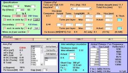
OK, made some transformers for the 801 amp described here: http://www.diyaudio.com/forums/showthread.php?postid=1551490#post1551490
The design is shown in the attached pic.
I learned at least two things:
I can make transformers
There's more to it than meets the eye.
The first transformer I made had a hf roll off around 60kHz, and very nice 10kHz square wave - nice shape and just a little ringing. I didn't do a very good job of getting the margins for the secondaries, as described by Bud. They tended to cover the bobbin end to end. I got better on the second wind, and everything was a little neater. But the performance was worse - 41kHz roll off. OK, let's try a third, neater still. This one had the 3dB corner at about 35kHz.
Now, I'd rather duplicate the first, but either of the last two is probably OK. However, I don't like the variation, as I should think that consistent phase response is desireable for good stereo imaging.
I like these little amps, and I think they deserve some good iron. It was fun to wind up a couple of OPT's but I don't want to spend much more time learning the subtle nuances necessary to get consistent results, much less shoot for a specific target. May have to get a couple of cores wound up. Bud?
Sheldon
Attachments
Sheldon
The last number is about what I would expect from offset margins. We use a close tolerance slit tape to fill in the margin area and wind without layer paper, in a bobbin form.
For our use we get the first phase deviation beginning about 35 kHz and FR at about 40 kHz with -3dB FR at 45 kHz. Once you can hold the margins exactly throughout the secondaries in the winding, your deviations will stabilize.
The bobbin walls define the primary winding width in our products and the secondaries are z wound with a 3mm offset. Most secondaries are single layers, that are hooked up in parallel or series outside of the coil, when connecting leads to the coil. I do not think this scheme is any good above about 800 VDC, with attendant AC swing voltages, and we don't build coils for duty beyond that point.
I am assuming here that you are winding with layer to layer insulation papers? Also assuming that your margins are for every layer? I do need some more information about how you actually constructed the coil.
Welcome to the fraternity! And feel free to PM me if you like.
Bud
BudP said:Sheldon
The last number is about what I would expect from offset margins. We use a close tolerance slit tape to fill in the margin area and wind without layer paper, in a bobbin form.
For our use we get the first phase deviation beginning about 35 kHz and FR at about 40 kHz with -3dB FR at 45 kHz. Once you can hold the margins exactly throughout the secondaries in the winding, your deviations will stabilize.
The bobbin walls define the primary winding width in our products and the secondaries are z wound with a 3mm offset. Most secondaries are single layers, that are hooked up in parallel or series outside of the coil, when connecting leads to the coil. I do not think this scheme is any good above about 800 VDC, with attendant AC swing voltages, and we don't build coils for duty beyond that point.
I am assuming here that you are winding with layer to layer insulation papers? Also assuming that your margins are for every layer? I do need some more information about how you actually constructed the coil.
Welcome to the fraternity! And feel free to PM me if you like.
Bud
Thanks for the reply Bud. I wound as follows:
500 turns primary, in several layers like a fishing reel. Tried to get close to one layer of wire with each pass across the bobbin. No insulation between passes. End to end layer.
Then one layer of high voltage fluorocarbon tape (about 0.03mm) and one layer of friction tape (about 0.3mm).
Then 48 secondary turns, single layer perfect lay, about 2-3mm margin on the ends, followed by the same insulation,
Then 1000 primary turns, then insulation,
Then 48 secondary turns, insulation,
Then final 500 primary turns.
Oh, and I put a piece of the high voltage tape over each lead coming out, where it could contact the other winding.
Sheldon
Hi Sheldon !
Great job indeed, and good results too !
You will probably obtain better (if really needed) hi freq response by splitting the primary so that the first and the last section be half the thickness of the inner one.
I suppose you already tried to use "SPLIT" button in the green area ?
I can't check myself cos I'm touring in CA 😉
This night Ventura, then to the north along the coast if there are no fires
Yves.
- Status
- Not open for further replies.
- Home
- Amplifiers
- Tubes / Valves
- OPT Design Assistante (EL84)