Hi folx,
Very good advices from BudP !
Let me point how you can exploit OPT_da to optimize the filling of the "copper window"
In the orange frame, the number of turns that fill fit in each single layer is computed and displayed as "Turns per layer Max", along vith the real number to put as "Actual".
This is true only if the size of YOUR bobin is as stated in the table, of course.
If you wind by hand, do not expect to be able to fit the "Max" computed turns, allow 5 to 10% margin for misaligned winding 🙄
(better to vaste some copper in winding "test" layer for each wire section you plan to use rather than to trash the whole "over filled" bobin).
Now, you can trim the wire diameter until each section fit in an integral number of layers. Observe the "Cu losses" and winding resistance (the "R" text boxes) while doing that to insure your not going to an "hot" tranny.
In the exemple you shown, the secondary winding is far for optimized.
Always try to occupy the whole width of the bobin, not only to have clean and flat base for the remainding sections, but also because the coupling at hi frequency (indicated by a low leakage inductance) is a direct function of the surfaces in regard.
Yves.
Bud
So, after two hour since your last post, thinking about
it all I understand what I think are the 2 most important
things:
A) Think about the section winding start and end, to
make this points combine where they have some output
wire. No solder points in any winding layer.
B) Calculate the use of surface of each layer to complete
it the best way possible.
I made a simple draw (top view) about the project of a
opt with primary in 2 parts and the secondary between
this primary parts. Ex: P/S/P
http://server7.pictiger.com/img/691253/picture-hosting/exemplo-opt-.gif
Yves
If I understand the correct surface use, I need a
copper wire that completes the winding layer in
a almost complete way. So take a look with a .7
wire for secondary:
http://server6.pictiger.com/img/676914/picture-hosting/opt-yves-2--.gif
Thanks again for all your patience friends
Blindsjc
Right !
Now you probably no longer need two wires in parallel at the secondary.
Removing one will not objectionally increase Cu losses (I try to stay below 10% for AC losses).
The good news being that this will slightly reduce the leakage inductance !
Much more remaining to say, specially looking at the size of the iron if this OPT is intended to go into a guitar amp.
Try with an EI84A (means: same lams but just 30mm stack height) 😉
Yves.
Yves,
I made some tests with EI84A but didn't find
a simple configuration like 84B. I will verify if
the supplier haves some other EI types. By
now I'm building a winding machine to start
with some pratical tests.
I want just to say thank you for all of you
my friends (specially Yves and Bud), I learned
a lot, and don't know how to show how much
you helped me. I know thats a lot more to know
about opts and will come back with new questions
for sure. Now is time to adventure!!!
Thanks a Lot
Hi friends, topic back to life...
From the study, new questions...
I have a project ok for test, but want to know
more and more about, so these are the things
that I still searching for.
First: To use the OPT with precise core values
I need to know the "MPL" parameter and weight.
So, after search a lot in the web I didn't found
any info about this type of calculation. I have the
width, tongue, height, but how to know this other
values? Any math calc can be used?
Second: Some additional information about
the parameters like AC Only, the the percentage
in parenthesis and the dB value in parenthesis
too.
Thanks a lot again
Blindsjc
blindsjc,
MPL is magnetic path length. Weight is in grams per 1000 pcs in most books. You then find the thickness of a single piece of core and divide the stack height by that thickness for # of pieces. I only have Americana Standard lamination specs, but you should be able to find data sheets on metric lams with this information.
Note that different grades have slightly different weights. Thats different grades of doped steel, for more permeability for a given flux density and more flux density allowed before saturation and less watts lost per pound of core material, for a given flux density, and less exciting power required also. Just take these as a given. Later I will tell you how to get performance, for an audio transformer, that allows you to use the worst grade of core, rather than the best.
Bud
Hi,
For standard "scrapless" lams, it's equal to twice the lenght of the "I" part.
In such lams, the flux divides in two equal "loops" both sharing the central leg of the "E" part (that's why it is twice the size of each lateral leg).
Weight, here, is the total weight of magnetic material needed for that specific core.
This show the copper losses for the signal only in contrast with "Tot" just at left wich incude DC in primary.
Parenthesis ?, mmh, don't know why I choosen that, but the first number is the power loss in Watts, the second in percent vs the full expected power and the third in decibel.
Yves.
Well, as BudP stated, MPL is the Magnetic Path Lenght, in other word the lenght of the path for the magnetic flux tru the core.blindsjc said:First: To use the OPT with precise core values
I need to know the "MPL" parameter and weight.
For standard "scrapless" lams, it's equal to twice the lenght of the "I" part.
In such lams, the flux divides in two equal "loops" both sharing the central leg of the "E" part (that's why it is twice the size of each lateral leg).
Weight, here, is the total weight of magnetic material needed for that specific core.
Second: Some additional information about
the parameters like AC Only, the the percentage
in parenthesis and the dB value in parenthesis
too.
This show the copper losses for the signal only in contrast with "Tot" just at left wich incude DC in primary.
Parenthesis ?, mmh, don't know why I choosen that, but the first number is the power loss in Watts, the second in percent vs the full expected power and the third in decibel.
Yves.
Thanks again friends,
I think I'm in love with opts haha...
I think that exists a legendary view
about this little iron cubes. I still
digesting all the information from
this topic and RH4, and want to learn
how to do this right.
Thanks for your help again.
PS: I just finished a Tube project
(schematic) based in a lot of other
projects like Soldano Atomic, and
ax84 lead, with a modded tonestack.
So, if there's any interest, I would
be very happy with any comment.
Just drop-me a line if any of you want
talk about it.
Ah, my first OPT is intended to be
used with this tube amp.
Blindsjc
blindsjc,
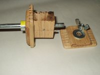
Here is a pretty simple to make winding form, that can be used for open wall, paper section, or bobbin with walls, winding. The wood is all oak sheet, with the grains at 90 degrees between end panels and supports, for strength. The center section is glued together and final sanded (and is actually square, though it does not look like it in this pic).
Hardware is a long bolt with the head cut off, a screw lock collar to hold the back plate up against the center block, and three tension pins. One in the central block back end, into the plate held by the collar, one through the bolt and out both sides into the central block and the one you can see that locates the removable plate.
We use these wooden winding forms exclusively now, having moved from all metal ones .They are cheap and easy to make, with simple tools and materials from your local hardware supply store, if that is what you call them where you live.
This sort of winding form will eliminate many of the difficulties you will run into while learning this art form. All of our hand fed winding machines have drill press chucks and the long bolts we use are 8 mm in diameter, so they fit in and can be clamped using the drill chuck key to tighten it .
Bud
Attachments
Hi Bud,
Thanks friend, this will fit perfectly with
the diy winder that I'm building, I was lost
in how to keep the reel secure while winding,
your idea kills the problem.
Take a look:
http://server6.pictiger.com/img/688711/picture-hosting/diy-winder-.gif
At the (A) will be the source of copper wire.
The wire pass in a pressing wood (D) with a
soft clothe that keeps it in some tension.
And then is winded at the (B) where I will
use your solution.
Finally, the (C) is a mechanic counter that
works when the (B) is winding to keep track
of the turns.
I will put some pics when it's working.
Thanks again friend
Blindsjc
blindsjc,
I am going to assume you are left handed and plan to sit between the tension device and winding arbor?
If you actually need a tension device you may find that felt pads, the very fine felt used for grease seals in some equipment, squeezing from both sides will be best. You will not need any more tension than that supplied by your fingers guiding the wire, for most wires.
You will want a drag on the spool also, just to keep it from over running and jerking.
Eventually you will put a large diameter pulley on the winder and a tiny one on a 1//8 horse power brushless AC DC motor. This will cause you to learn how to build a solid state infinitely variable motor controller, using a guitar amp Wah pedal as the potentiometer.
Then you will be like the rest of us.
You should not spin fine wire spools. If you leave the paper wrapper intact, mount a ceramic eyelet on a piece of wood and clamp the wood on top of a plastic bucket, to confine the wire whip between spool and eyelet, you will have a better dereeler than a spinning wire spool. Twisting the wire is not important here. In fact, after a number of battles with magnet wire, trying to get it to do what you want it to, you will begin to feel satisfaction in twisting it
If you want pics of simple production equipment, as you try to find answers to the problems that you will face, I can provide them.
Bud
BudP said:
. . .
You should not spin fine wire spools. If you leave the paper wrapper intact, mount a ceramic eyelet on a piece of wood and clamp the wood on top of a plastic bucket, to confine the wire whip between spool and eyelet, you will have a better dereeler than a spinning wire spool. Twisting the wire is not important here. In fact, after a number of battles with magnet wire, trying to get it to do what you want it to, you will begin to feel satisfaction in twisting it
If you want pics of simple production equipment, as you try to find answers to the problems that you will face, I can provide them.
Bud
Hi Bud,
I can't figure how this dereeler works !
Some pics could prove useful.
At this time, I just left the spool on the ground with the axle vertical and put a large glass cup reversed onto.
But some twisting probs remain occasionally

Many thanks for already mentionned tricks and tips.
Yves.
Interesting thread!
It's also in my plans to build a custom winding machine.
I have found a motor from junk that was used as sewing-machine!
And I have kept it to use it in the future for winding.
Sorry for the OT but Bud, maybe you can help me in an other thread
I have post for measuring chokes. I'm trying to build a jig for measuring chokes....
Burning the Brain
Hi again friends,
So Bud and Yves, I know thats a lot boring to you,
but now I have the final model I plan to build and
I ask you for a look at it.
I used the same core for power and output
transformer, since I know thats a available
core at my supplier this will make the constructions
a lot easier to me, not too much options. Sure I
will change the core if this can't have a good
performance, but if the performance can be
good this way... lets use it.
I calculated the MPL and AFE etc. So, I think these
values can be wrong, I made it with a lot of attention,
but you know... first time.
And finally, thanks a lot for any reply and info.
Core Data:
http://server5.pictiger.com/img/1410656/picture-hosting/core-test.gif
Power Data:
http://server4.pictiger.com/img/1413208/picture-hosting/power-test.gif
Output Data:
http://server4.pictiger.com/img/1413215/picture-hosting/opt-test.gif
Thanks again
Blindsjc
blindsjc, sorry that I'm hijacking your thread. But hope my questions are usefull for your adventure too.
Bud,
You are using these wooden winding forms for transformers with custom bobbins, right?
Why don't you use the ready plastic bobbins?
Can you describe us how you build the custom ones?
Thanks in advance! 🙂
Bud,
You are using these wooden winding forms for transformers with custom bobbins, right?
Why don't you use the ready plastic bobbins?
Can you describe us how you build the custom ones?
Thanks in advance! 🙂
No problem resident,
But I think thats just a support where the
plastic bobbins are connected while they
are winded. I'm building a winder too, and
you need this type of support do keep the
bobbin secure while turns are counted and
copper is winded.
Thanks
Blindsjc
But I think thats just a support where the
plastic bobbins are connected while they
are winded. I'm building a winder too, and
you need this type of support do keep the
bobbin secure while turns are counted and
copper is winded.
Thanks
Blindsjc
Some stuff to dig into:
http://www.dissident-audio.com/Pst/Bobineuse.zip
http://www.dissident-audio.com/Pst/Pst.zip
http://www.dissident-audio.com/Pst/DocPst.zip
http://www.dissident-audio.com/Pst/SE-WINDUP.zip
Sorry for the mess and French language, photos and schemos may help anyway.
Yves.
http://www.dissident-audio.com/Pst/Bobineuse.zip
http://www.dissident-audio.com/Pst/Pst.zip
http://www.dissident-audio.com/Pst/DocPst.zip
http://www.dissident-audio.com/Pst/SE-WINDUP.zip
Sorry for the mess and French language, photos and schemos may help anyway.
Yves.
Hi friends,
Any comments about the
project of power and output
transformers that I uploaded?
Thanks
Blindsjc
PS: Thanks for the docs Yves.
Any comments about the
project of power and output
transformers that I uploaded?
Thanks
Blindsjc
PS: Thanks for the docs Yves.
Hi Guys,
The wooden form is to support the bobbin, very snugly, to keep the wire from deforming the bobbin during winding. This will help keep the bobbin from being deformed later, after it is off of the winding form and the wire begins to relax and change the pressures within the winding. We use onlycommercially available bobbins as our transformers are all CE 6500 safety standard rated.
blindsjc,
Oddly I cannot make much sense from the pictures of the program. I would have to start the design process myself. Also, I am the typical language poor american and do not know what the terms next to the windows mean. I can guess, but I would need to have your files, load them into an english language version, and work through the numbers to comment.
Having said that, I design guitar amp powers for a 3% regulation, no load to full load. This one characteristic will control everything else about the power transformer. The power transformer controls a great deal of how the amp responds and this one factor frees the amp from sag induced time lag and loss of dynamics..
For the Output, the -3 dB point should be 40 Hz, based upon the reactive inductance used to match Rp plus Rl, added in parallel, and the primary DC resistance added in series.
One of the controls for tone character is where you place the peak permeability in the power band. Placed at half power you are then going to run a bit lean in tone character as you reach for full power. But, putting that peak up higher in the power band will give you stronger bass as you play louder. one is not better than the other, just another parameter to use. Peak perm is at 3.8 Kg and you can find out how to use it by using the perm curve in the RDH4.
I have attached the first page of our data packet, and it gives a description of all of our "voiced" transformers. These are from players, not spectators, and we voice them for the players not an audience, as we are aware we make only one part of a musical instrument.
If anyone is interested in the entire data packet, which has specs for the guitar transformers please PM me and I will forward it to you. It will give you an idea of what sizes and DC resistances, truly brute force, bullet proof, guitar transformers have.
Bud
Attachments
- Status
- Not open for further replies.
- Home
- Amplifiers
- Tubes / Valves
- OPT Design Assistante (EL84)