Yves,
Your little program encourages me to try a couple of OPTs. I think I have most of it figured out, but have one question (for now). Your calculation of wire sizes (actual) seems to account for the outer diameter of the wire, as it adjusts the layers according to how many turns can fit. How does it account for the insulation thickness to get the actual copper cross section so that it can calculate resistance?
Sheldon
Hi Sheldon,
Electrical calculations are based on the effective copper diameter (displayed values) while mechanical ones include the thickness of the insulating varnish for grade 1 wire.
A preliminary check on a single layer pays more than the cost of the vasted copper .
Yves.
Electrical calculations are based on the effective copper diameter (displayed values) while mechanical ones include the thickness of the insulating varnish for grade 1 wire.
A preliminary check on a single layer pays more than the cost of the vasted copper .
Yves.
Hi Yves!
Would it be possible to use your excellent OPT DA program for calculating Toroid OPTs??
Greets:
Tyimo
Would it be possible to use your excellent OPT DA program for calculating Toroid OPTs??
Greets:
Tyimo
Thanks Yves,
I assumed that, but wanted to confirm.
I'll follow your suggestion. But first I need to order some wire and get sizing as close as possible. Then a winding check will tell me if I have to make some adjustments.
Oh, I knew that I'd have another question: I don't quite understand the single/parallel format for your program. I'm planning on a 6 or 7 watt SE transformer. For interleaving, I'm looking at winding three primaries and two secondaries. Both the primary and secondary would comprise a single winding in series. However, I could choose to wind each secondary layer as bifilar paralleled wires of smaller diameter, instead of a single larger wire. It might give me a better fit. How would I enter that configuration, or can I calculate that?
Sheldon
Yvesm said:Electrical calculations are based on the effective copper diameter (displayed values) while mechanical ones include the thickness of the insulating varnish for grade 1 wire.
I assumed that, but wanted to confirm.
Yvesm said:A preliminary check on a single layer pays more than the cost of the vasted copper .
I'll follow your suggestion. But first I need to order some wire and get sizing as close as possible. Then a winding check will tell me if I have to make some adjustments.
Oh, I knew that I'd have another question: I don't quite understand the single/parallel format for your program. I'm planning on a 6 or 7 watt SE transformer. For interleaving, I'm looking at winding three primaries and two secondaries. Both the primary and secondary would comprise a single winding in series. However, I could choose to wind each secondary layer as bifilar paralleled wires of smaller diameter, instead of a single larger wire. It might give me a better fit. How would I enter that configuration, or can I calculate that?
Sheldon
Tyimo said:Hi Yves!
Would it be possible to use your excellent OPT DA program for calculating Toroid OPTs??
Greets:
Tyimo
Unfortunatly the geometry of a toroïd is very different so that the calculated space used by the wires will be wrong and unusable.
Moreover, capacitance and leakage between windings will also be affected.
You just can use the program to compute turns number and estimate primary inductance.
But since the permeabitlity and the allowed induction will also be higher than thoose of standard lams, it should be necessary to create another .dat file if you can obtain the values to put into.
I do not have data, the ones for EI lams you will find in the std.dat and M6X.dat was measured by myself on prototype bobins and lams.
Can't help more, sorry !
Yves.
Sheldon said:
. . .
Oh, I knew that I'd have another question: I don't quite understand the single/parallel format for your program. I'm planning on a 6 or 7 watt SE transformer. For interleaving, I'm looking at winding three primaries and two secondaries. Both the primary and secondary would comprise a single winding in series. However, I could choose to wind each secondary layer as bifilar paralleled wires of smaller diameter, instead of a single larger wire. It might give me a better fit. How would I enter that configuration, or can I calculate that?
Sheldon
You define interleaving by specifying the number of sections for both primary and secondary.
f.e., 2 sections in serie by 2 in parallel means a total of 4 sections.
Most of the time, paralelling is not necessary at primary but usefull ar secondary.
At the secondary, you have the additional option of using more than one wire for EACH section, just because, as you pointed, this may be useful to optimise the filling.
So, to follow your plan, you could specify 3 sections by 1 in parallel for the primary, and either 2 sections in serie by 1 in // or 1 section in serie by 2 in //. Just your choice.
In addition you may specify 2 wires in // per section if you plan to wind bifilar (or more if you want !)
Oh, and check how splitting a section in two halves dramatically reduces the Leakage inductance (as N.H.Crowhurst told) !
Yves.
Yvesm said:You define interleaving by specifying the number of sections for both primary and secondary.
Yes, got that.
Yvesm said:f.e., 2 sections in serie by 2 in parallel means a total of 4 sections.
Got it - I hope. Sorry if I'm a bit dense. If, f.e., these are primary sections, there would be 4 sections, with secondaries between them. They would then be connected like resistors in series/parallel, or speakers in series/parallel, so the resistance would be equal to one section.
Yvesm said:At the secondary, you have the additional option of using more than one wire for EACH section, just because, as you pointed, this may be useful to optimise the filling.
So, to follow your plan, you could specify 3 sections by 1 in parallel for the primary
So 3 sections by 1 in parallel, just means three sections in series, no? I assumed that this must be the case, as it won't allow 0 sections in parallel.
and either 2 sections in serie by 1 in // or 1 section in serie by 2 in //. Just your choice.
[/B]
To restate, 2 sections in series by 1 in //, simply means two sections in series - yes?
And, following the same convention, 1 section in series by 2 in //, just means two sections in parallel.
So for my case of having two secondary sections, I can wind them with a single wire (2 sections in series, 1 in //) or wind them with two wires each section, connected in parallel for each section, with the two section connected in series (2 sections in series, 1 in //, 2 wires in // per section). The option of multiple wires in // per section is only applied to the secondary - yes?
If I'm making sense, then I think I have it.
Once again, thanks for this nice program and for the help.
Sheldon
Yvesm
Do you have a link to or a copy of the document? I would be very interested to read, ponder and explore the implications.
Thanks,
Bud
Oh, and check how splitting a section in two halves dramatically reduces the Leakage inductance (as N.H.Crowhurst told) !
Do you have a link to or a copy of the document? I would be very interested to read, ponder and explore the implications.
Thanks,
Bud
Hi Bud,
You may find some material in RDH4 chapter 5.3(IV).
I've some links and papers in the deep of my hard disk !
Let me time for digging.
You can see the result by clicking on the "split/equal" buttons in the green frame.
Measures confirm.
Sheldon,
I beleive you got all 🙂
Yves.
You may find some material in RDH4 chapter 5.3(IV).
I've some links and papers in the deep of my hard disk !
Let me time for digging.
You can see the result by clicking on the "split/equal" buttons in the green frame.
Measures confirm.
Sheldon,
I beleive you got all 🙂
Yves.
Bud,BudP said:Yvesm
Do you have a link to or a copy of the document? I would be very interested to read, ponder and explore the implications.
Thanks,
Bud
You can download it from
here
Hi friends,
Wow, this topic wold become a book.
If Bud or Yves write a book, the first copy
is mine...ha.
So, about the RH4, I found a better definition
scan than pmillett.com on the emule (peer to
peer program). So, if someone is using the
program is a good alternative. But pmillett.com
haves a lot of interesting books that you don't
find any other place 🙂
and...after a lot of trouble to find the right pieces
to make my own I decided to buy a small electric
winder, man, I can't wait to start my tests.
The toy:
http://www.cisel.com.br/Bobinadeira_Pequena_Finalizada.jpg
Again, thanks a lot for all the info, I still
reading the topic and learning a lot.
Thanks friends
Blindsjc
wow that's a cool jig! Does it have a motor or it's manually?
It looks like, the black thing at the right is a pedal that controls the speed from the motor....
It looks like, the black thing at the right is a pedal that controls the speed from the motor....
Thanks Resident,
Yeah, it haves a pedal and it controls the
electric motor speed. And it aves a light right
above where you have the winding. Think it
will handle my needs for a long time, but is
a expensive toy... R$ 590,00. That's about
US$ 320,00 today. Man... in Brazil everything
is really expensive.
Thanks
Blindsjc
Found two papers from Crowhurt here:
http://www.audiofaidate.it/materiale/20_030_040_001_crowht_outtrafoI.pdf
http://www.audiofaidate.it/materiale/20_030_040_001_crowht_outtrafoII.pdf
Yves.
http://www.audiofaidate.it/materiale/20_030_040_001_crowht_outtrafoI.pdf
http://www.audiofaidate.it/materiale/20_030_040_001_crowht_outtrafoII.pdf
Yves.
resident said:
Yves, I have visited this site but I can't find info about the materials.
If they are M6 , M19, M50 ...... The only thing I can understand is that the first laminations are 0.50mm thick & the second one 0.35mm.
resident,
It seems that the 0.50 mm lamination is the "standard" lamination (max. flux density of 1 Tesla), while the 0.35 mm is grain oriented lamination (it says "lamierino grani orientati") equivalent to M6 grade (max. flux density of 1.4 Tesla).
Yvesm,
Thank you for the links to those two papers. If you come across more from this series, links would be appreciated by me and benefit everyone involved here. I will do the same.
Bud
Thank you for the links to those two papers. If you come across more from this series, links would be appreciated by me and benefit everyone involved here. I will do the same.
Bud
I just found this interesting thread.
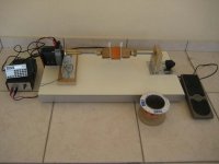
Here is my DIY winder. It's a 24V DC motor fed by a PWM variable speed controller. The foot-switch is just an ON-OFF switch, varying the speed is controlled on the PS box. Turns counter is implemented with the aid of an old calculator and a reed switch activated from a magnet on the shaft.
To have a controlled uniform winding, winding speed cannot be higher than 12 rpm. The wire is fed by hand. It's kind of Zen winding an OPT, but I enjoy the process. It cost nearly nothing, as most of the parts were salvaged from older stuff.
Attachments
- Status
- Not open for further replies.
- Home
- Amplifiers
- Tubes / Valves
- OPT Design Assistante (EL84)