Thank you for clarifying.waltube said:As I told in a different thread, FIAT give me the proto I ask and I paid for them. That's all.
Every info about the product they have are on FIAT site or can be obtained with an email to them.
The only 'opinion' I have expressed in this thread is that real transformers are different from perfect transformers. In what sense is this "out of logic"? One of the benefits of science and civilisation is that we can learn from others, so we do not personally have to carry out tests on all possible pieces of apparatus in order to have a reasoned view on their behaviour.The opinion of DF96 are absolutely out of logic and I am waiting the results of tests that he can do if he has the capability.
Thank you for clarifying.
The only 'opinion' I have expressed in this thread is that real transformers are different from perfect transformers.....
That was a redundant remark 😀😀
A good trick to master is to design the transformer in such a way, that the Cp/Ls resonance has a lowest Q possible,
resulting in a lower as possible phase shift and FR amplitude alteration.
resulting in a lower as possible phase shift and FR amplitude alteration.
A good trick to master is to design the transformer in such a way, that the Cp/Ls resonance has a lowest Q possible
Not necessarily. Over-damping self-resonance causes earlier high frequency roll-off, thus limiting transformer's frequency response on the high side. There is optimum damping, at which resonance peak is the lowest and high frequency response is the most extended. This is nicely shown by a graph on Jim Hagerman's web site (the last picture on the page):
Hagerman Technology LLC: Cartridge Loading
This is about phono cartridge resonance, but the same principle applies to an output transformer.
sser2, you have a point. I forgot to mention that in practice, it's hard to overdampen a Ls/Cp resonance, so I never worried about such a FR roll-off.
A more significant roll-off would sometimes be the Ra-Cs, when Cs comes in to play with a grounded secondary.
A more significant roll-off would sometimes be the Ra-Cs, when Cs comes in to play with a grounded secondary.
Hi Jazbo8
Are you in hurry? 🙂
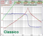
The value of R are the parasitic value of the resistive component in serie with the reactance.
In theory less are these value, for the same frequencies and same value of H, better is the quality of the trafo.
Walter
Are you in hurry? 🙂
The value of R are the parasitic value of the resistive component in serie with the reactance.
In theory less are these value, for the same frequencies and same value of H, better is the quality of the trafo.
Walter
So the R value has nothing to do with the impedance plot below. Just want to know how to read and interpret the data given. Is the software available? I'd love to try it with my own OPT's. Thanks.
Yes.
I am pushing with Fabrizio about this software but at the moment it is in beta test.
I love it but we have to wait.
Walter
I am pushing with Fabrizio about this software but at the moment it is in beta test.
I love it but we have to wait.
Walter
The value of R are the parasitic value of the resistive component in serie with the reactance.
In theory less are these value, for the same frequencies and same value of H, better is the quality of the trafo.
Again, not necessarily. High DC resistance of winding may increase damping of transformer's self-resonance, lowering the high frequency response peak. In one particular case, unloaded secondary of an interstage transformer, high DCR is pure goodness without any disadvantage.
1. I use a large output voltage 50 Ohm signal generator to drive the Primary directly; or the same generator with a series resistor that is equal to the expected rp of the tube I will eventually use (I do not calculate in the 'extra' 50 Ohms, because the tube rp may be that large).
I put probes on the primary and secondary. I test with; and without the secondary loaded. I measure the voltages and phases under the 4 connection combinations listed above.
There is no DC in these tests, but the transformer would not likely be significantly better when we add the DC component for most measured and calculated results of these 4 test connection setups.
Then I set the generator to sine, and to square wave modes for various tests.
Frequency response, phase, turns ratio, insertion loss, inductance, resonance, and square wave response: rise time, fall time, ring, slope and overall shape are some of the tests resulting from these 4 setups.
I have not tested the transformers "backwards" I would need a solid state amp to do that.
And if I did, some of the tests would require connecting the solid state amp directly to the secondary (some solid state amps might not like that).
2. Now, I build the output stage, with the power tube(s), and output transformer, and test
frequency response, distortion (harm, 2nd/3rd IM), damping factor, gain, rise and fall time, clipping at midband, and low frequency wave shape at large signal, etc.
3. Conclusion: I usually get similar results in 1. versus 2. above. Unless something went wrong, it should be that way.
Keep in mind that if you use quiescent current near the transformer's maximum rating, and check the low frequency performance, then 'Your mileage may vary'.
 The bi-wiring discussion is worthy of its own thread, and some posts have been moved to:
Bi-Wire Ideas from Broskie
Some points:
1- the use of the "backward" connection is very simple, just to have a good ss amp.
The main problem on test in deep the trafos is to have on primary a large swing on tension with a very low distortion and, possibly, the Zout of the generator compliant with a Z we decided to use.
If we can consider 100 vrms as a good value (more will be better) this means that the Vpp will be 285 volt, very hard to have.
With ss amp we need jut to put in series on the secondary the value of the nominal load want to use and on primary the nominal load related to the ratio of the trafo.
For example ( as I described about the three trafos), with 8 vrms on 8 ohm we have 8 watt, a tipycal power for a 300B s.e.
Most of the ss amp can delivery this power with a very low distortion; if we have a trafo with1:20 ratio , on primary ( acting as secondary) we have ( in theory, attention!) 160 vrms (=451 v p-p) and this became very interesting to study the trafo, of course with a minimum of test set.
2- to have an idea about the quality of the trafo, in this case s.e., is not necessary to have a bias current, for a simple reason, because if a low frequency ( where the iron has a great importance) I check, in this situation, that the L is relative low so the Z is also low so the coupling with tube can generate an attenuation and an increasing of distorion, with a bias current the situation will be worse.
This can be a semplicistic concept but it is very practical; in fact in Audioreview all the tests on s.e. trafo are done with a method described and no bias current.
The results with the entire amp confirm this.
to 6A3
why you have to connect the ss amp directly to the secondary?
Walter
I use a 50 Ohm signal generator to drive the primary. I drive it with 50 Ohms for some tests, and for other tests with 50 Ohms + R = rp of the tube I will use in the completed amplifier.
Some of the suggested tests mentioned earlier in this thread were using a SS amp (which typically have a very low impedance/high damping factor), and putting it in series with a resistor that is equal to the output tap rating of the transformer under test. The thread suggested driving the output tap of the transformer that way. OK.
I do not have a SS amp. And, as I said, I do not want to drive the secondary (output tap of the transformer under test).
I do not think it is a good idea to use a moderate damping factor tube amp with its own transformer and no negative feedback, plus a series resistor to drive the secondary of the other transformer that is under test.
That kind of tube amp used as a "signal generator" may not have a constant damping factor, may not have perfect square wave response, and may not have perfect frequency response, etc.
A good signal generator, and a signal generator with a series resistor added, are far more predictable. You want to drive the transformer with a known signal, not one that has already gone through many / most vacuum tube amps.
Driving the transformer secondary with a series resistor does not work for some of the tests that I would do. You have to remember that the transformer secondary impedance is not the same as its rated impedance at some frequency extremes, especially at very low frequencies.
It is much easier to drive the primary with a signal source impedance that is far lower than the primary impedance, and is even lower than the DCR of many transformer primaries.
I go through the math and setups when I actually test, and I can not remember the specific test(s) at the moment. I would hopefully remember if I were actually doing the tests next time. The idea is to swamp out some of the transformer's characteristics, to make something drop out of the equations. You get better accuracy for that test(s).
I hope that make sense.
Last edited:
Hi
I am not agree with your point of view.
The main purpose of the test as I describe is to have the main info of the trafo only.
I don't know which type of generator you have, if it is capable to generate a great swing with a THD = 0,0 ...something it is ok but it is very hard to have.
In Audioreview is planned in the future to test a Fet amp generator with a nominal Vout of about 200 vrms with a very low distortion.
I hope that some readers of this thread can test the trafo with the method I have described and then send the opinion about this.
Walter
- Home
- Amplifiers
- Tubes / Valves
- OPT Characterization