I bypass them with modified Wima .33 polyprops (steel leads dremeled off and 6N copper leads installed and then marked for outside foil orientation and installed with the outside foil going to the output....pics on my website) and install WA-Quantum chips on them. Sounds like $100 fully burned in Teflons.....maybe better. You also want to remove the 50K resistor to ground after the cap. You don't need it and they sound bad. You don't want the bypass caps dangling in the air....they should be mounted with a little Amazing Goop. Double stick tape sounds really bad!
I bypass them with modified Wima .33 polyprops (steel leads dremeled off and 6N copper leads installed and then marked for outside foil orientation and installed with the outside foil going to the output....pics on my website) and install WA-Quantum chips on them. Sounds like $100 fully burned in Teflons.....maybe better. You also want to remove the 50K resistor to ground after the cap. You don't need it and they sound bad. You don't want the bypass caps dangling in the air....they should be mounted with a little Amazing Goop. Double stick tape sounds really bad!
I'm finding more and more caps are coming with steel leads 🙁.
I was recently doing a Dumble ODS guitar amp clone, trying to replicate the
original caps used, the newer caps of exactly same brand / number / type
all had steel leads. Had to do the same, snip snip - damn frustrating.
If you need a cap in the signal path and need a perfect reference, insert a
Duelund VSF, that will tell you what it should sound like. Then try to find
something that comes closest to them. They are pretty much as good as it
gets - but too expensive.
But as Joe states, better off ditching them altogether if possible.
Nothing like nothing 🙂
Z
OK, so a direct output cap replacement is problematic. I like to keep things simple, but I cannot remove them, sadly.
I'm currently trying out some fancy regulators in a preamp. I might want to try them in the 105 too, but I had some difficulty identifying the regulators used in there. I could see a pair of LM316/317 and I assume these are used for the output stages, ot not? There's another pair at the end, in huge heat sinks, and a single one in the middle. The middle one could be the supply for the Sabre, or not?
Has anyone of you managed to identify these other regulators, and do you happen to know what feeds what? And then, obviously, the question is which ones would be the best candidates for upgrade. I'd guess the DAC regulation, but the professional modders don't seem to do that one, or do they?
Interesting. Got the cheaper BDP-103 on my bench.
The Mainboard is the same of course, but the DAC/Analog board is based on CS4382A DAC. On all eight channels, the outputs from the DAC goes through electrolytic capacitors. This is before 5532 opamps. There is a 2.5V offset there. There is 10mV offset on the inputs of the opamp (checked L and R) and 20mV on the output and... another electro cap before RCAs.
Oh well.
I am connecting 1:1 transformer across the two phases - no DC will go through the two transformers I'll be using - and should get about 2.3V outputs. These voltage DACs have fairly low output Z (unlike Sabre) and perfect for 1:1 transformers. Disconnect RCA from board and wire the secondary there.
Cheers, Joe
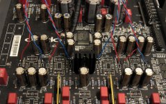
Hi Guys
Just thought I'd post the photo below. Maybe some of you (Rick?) have noticed the slightly 'scrambled' way the phases/layout is arranged - the DACs outputs are paralleled and doubled up on the unbalanced stereo and are only single on the balanced. The fourth is of course for the headphone section.
Peculiarly, the unbalanced Stereo, the I/V converter resistors are not the same on both phases: 1K2 and 530R - so about 2:1 - asymmetrical. This gets summed of coursed and would be similar output level identical 865R ((1200+530)/2=865).
This explains the 2 x 1K8 (very similar to 1200+530) I/V resistors on the balanced (XLR) gives almost the same output per phase.
So note in the picture below that two Reds are paralleled up, as are the two Blues - this applies to both channels.
Cheers, Joe
Attachments
May I add a correction, I dumped outputs into 3R3 and got 863mV (RMS) on both.
Also the gain resistor I use in my post DAC circuit that controls gain, needs to be doubled to get same output approx.
This means there are no paralleled phases at all. I have added two phases together in the photo in #306.
So where in the Oppo 95 where I had four parallel phases, in the Oppo 105 that is reduced to two in my case/upgrade. There is a third phase for the headphones, that leaves one phase unused. Not sure what they have done with it, is it open circuit or grounded? Haven't traced that yet.
Cheers, Joe
Has anyone looked for ground loops designed into the circuit board traces of the 105?
Not yet as I know... Have you more infos about or is an only question?
Last edited:
Only a question. I just got mine yesterday and from my experience with other circuit boards of this type there are usually ground loops everywhere. For some reason, few people who layout PC boards understand the huge impact of ground loops on the sound of an audio component.
Does anyone have a hi-res image of the trace side of the circuit boards? I would be willing to give it a go. I want to wait for a few weeks before I take mine apart.
Does anyone have a hi-res image of the trace side of the circuit boards? I would be willing to give it a go. I want to wait for a few weeks before I take mine apart.
Many people have concluded that the balanced outputs are superior to the unbalanced outputs.
For those of us with unbalanced amplifiers, it seems that a XLR balanced to RCA unbalanced cable would extract much of the benefit. I see that the balanced circuit uses one op amp for each left and right channel, while the unbalanced circuit uses a single dual op amp. This could explain part of the improvement.
For those of us with unbalanced amplifiers, it seems that a XLR balanced to RCA unbalanced cable would extract much of the benefit. I see that the balanced circuit uses one op amp for each left and right channel, while the unbalanced circuit uses a single dual op amp. This could explain part of the improvement.
The balanced output is superior to the unbalanced only when one use that with an unbalanced input amplifier. There is no any benefit to convert that balanced to unbalanced for use it so with a conventional amplifier. Using RCA output with an unbalanced amplifier is the only reasonable way and it have the max benefit for this type of output.
The logic about how many opamp are used to process the signal on one or another type of output, is not quite right. The right logic it may be: the less components on the signal path, the better for the integrity/quality of that signal...
Converting the balanced to unbalanced it cancel all the benefit of the balanced output. If one have only the balanced output on a device and it dispose only an unbalanced amplifier, then a such convertor do the job to connect those together and use it the system. But this is a temporary compromise solution, not something which it "would extract much of the benefit" of an balanced output...
My suggestion is to use it the right way and be happy with that benefit you can get so...
Last edited:
I have wrote wrong in the first phrase of the previous post...
Is right like this: The balanced output is superior to the unbalanced only when one use that with an balanced input amplifier.
I think is not quite well that this forum do not permit posts editing, but a half hour after the post is first published. Having continuous edit access to his posts, one may correct many of the published posts or just delete what it become unnecessary, and so it will be prevented too much (wrong) text in the threads...
Last edited:
Yes corus, I think you are right. On reflection last night I realized that one would probably need a transformer to convert the signal, as the two halves should be combined (The signal is probably unbalanced straight from the DACs). (Although as far as pickup,I should note that my cable is only 3 feet long). So how about if I do this using a transformer on the amplifier side, or should I instead think about ways to improve the unbalanced output?
Last edited:
Actually there are many other improvements one may have in place before thinking to convert balanced to unbalanced...
I too, do not have yet an balanced amplifier, and I have used all the time the unbalanced one. I have to say that I still have a very good sound this way. Anyway I want to switch to balanced amplifier. Is my priority now. I think is the right way I may use all the benefits of such output/connection.
So, my suggestion is you try (to forget that way with an transformer and so...) to get the most out of RCA output, doing the rest of quite many other mods which it may bring very real and important improvements in that unbalanced way. BTW, the most of the mods one may want to put in place, have common improvements for both ways: balanced/unbalanced. Then think to get an balanced amplifier... to go balanced with an already good modded device.
I'm using the BDP-105 with a transformer volume control (TVC), which can take balanced as well as single ended inputs with precisely the same hardware. I also think the balanced outputs on the Oppo are slightly better, and a TVC preamp is probably one of the best and most cost effective ways to utilise it. You can then still use a single ended power amp. Additional advantage is that you can break any ground loops, and TVC's can sound extremely good.
Help me out here. I am trying to understand the circuit topology for the BDP-105 analog driver single-ended output stage. Please correct me if I am wrong.
a. Output op amps are 5532.
b. Inputs and outputs to the 5532 are R-C coupled.
c. Output load resistor is 50K.
Q1: Electrolytic coupling caps are what values (both in to and out of the 5532)?
Q2: Input load resistor to 5532 is what value?
BTW, I have not run my output directly to my amp - not yet anyway. Still going through my Dared MC-7P tube preamp. The dared uses a DC-coupled input stage.
Has anyone shorted the caps on the output and had a listen?
/
So, I har a resounding - No!
/
- Home
- Source & Line
- Digital Source
- Oppo's BDP105 - discussions, upgrading, mods...